Recently Saudi Arabia released new LED standard SASO 2902 for energy efficiency, functionality and labeling requirements for Lighting products. We have got the SASO 2902 in 2017 which is draft and already produce some instruments for some of the Saudi Lab. Such as below products:
1. LPCE-2(9000B) High Precision Spectroradiometer Integrating Sphere System. It can test EEI, Energy Efficiency Class, SDCM, CRI, CCT, Lumen and so on.
2. LSRF-3 Lamp Start, Run-up time and Flicker Tester, which meet Table 13 (on page 27) in SASO2902. The LSRF-3 can be used with LISUN LPCE-2 High Precision Spectroradiometer Integrating Sphere System.
3. LSG-5000 LM-79 Moving Detector Goniophotometer. This test system can make the measurement of Luminous Intensity Distribution, Luminaries Efficiency, Luminance Distribution, Efficient Luminescence Angle, UGR and etc. The test result can be exported as CIE, IES, LDT and other format files.
4. SY2036 Aging and Life Test Rack which is special designed for Saudi Arab to meet SASO2902 in clause 5.2.
5. LEDLM-80PL LED Lumen maintenence and endurance test system, which meet SASO2902 in clause 5.2.
6. WT2080 LED Driver Test System
Lisun Instruments Limited was found by LISUN GROUP in 2003. LISUN quality system has been strictly certified by ISO9001:2015. As a CIE Membership, LISUN products are designed based on CIE, IEC and other international or national standards. All products passed CE certificate and authenticated by the third party lab.
Our main products are Goniophotometer, Spectroradiometer, Integrating Sphere, LED Test Instruments, CFL Test Instruments, Photometer and Colorimeter, EMC & EMI Testing, Surge Generator, Electrical Safety Testing, Environmental Test Chamber, Waterproof Test , Dustproof Test Chamber, High and Low temperature Humidity Chamber, Plug and Switch Testing, AC and DC Power Supply.
Please feel free to contact us if you need any support.
Tech Dep: Service@Lisungroup.com, Cell/WhatsApp: +8615317907381
Sales Dep: Sales@Lisungroup.com, Cell/WhatsApp: +8618917996096
Wednesday, May 27, 2020
Tuesday, May 26, 2020
Contents and Meanings of EMC Test According to International Standards
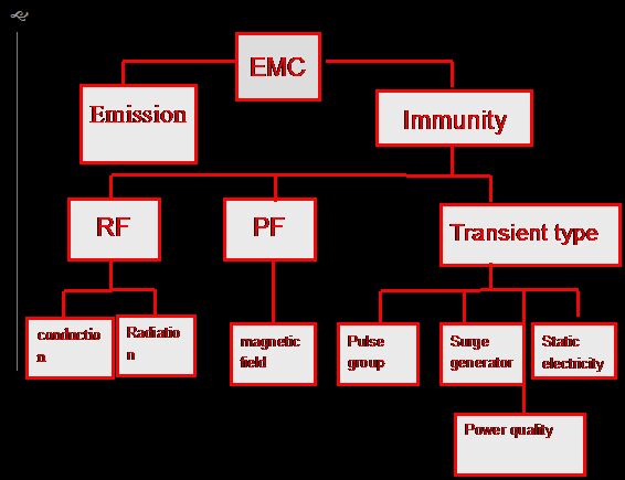
Electromagnetic Compatibility EMC refers to the ability of a device or system to function properly in its electromagnetic environment and does not constitute an electromagnetic disturbance to anything in the environment. Sensor electromagnetic compatibility refers to the adaptability of the sensor in the electromagnetic environment, maintaining its inherent performance and the ability to perform specified functions. It contains two requirements: on the one hand, the sensor should not cause electromagnetic interference to the environment in the normal operation process, and the sensor must have a certain degree of immunity to the electromagnetic interference in the environment.
1. Conducted radiation interference
The RF interference frequency range emitted by this standard covering equipment is 9KHZ-400GHZ. The limits in this standard are determined on a probabilistic basis so that disturbances are suppressed within economically reasonable limits while still achieving adequate levels of radio protection and electromagnetic compatibility. In exceptional cases, additional requirements may be made. The EMI Test System EMI-9KC/EMI-9KB fully meets CISPRl6-1, GB17743, FCC, EN55015 and EN55022.
EMI-9KA/9KB EMI Receiver System is a main test system for EMI (Electro Magnetic Interference) testing.
2. Static Immunity
The International Electrician Commission (IEC) has issued IEC 61000-4-2 version 2.0 (2008-12) entitled “Electromagnetic Compatibility (EMC) – Part 4-2: Test and Measurement Techniques – Electrostatic Discharge Immunity Test”.
This standard covers the immunity requirements and test methods for electrical and electronic equipment subjected to electrostatic discharge, including from equipment to direct operators, from personnel to adjacent objects. In addition, it defines the range of test levels for different environments and different installation conditions, and establishes test procedures. The purpose of this standard is to establish a common and repeatable benchmark for evaluating the performance of electrical and electronic equipment when subjected to electrostatic discharge. It also lists statics that may occur in objects near people and critical equipment, as well as typical waveforms of discharge current, test range, test equipment, test setup, test procedures, calibration procedures, and measurement uncertainty.
The second edition of the standard replaces the first edition published in 1995, and its amendment 1 (1998) and its amendment 2 (2000) together constitute a technical revision that is fully compliant with the basic IEC EMC guidelines 107.
Electrostatic Discharge Simulator (Electrostatic Gun) from LISUN is in full compliance with IEC 61000-4-2, EN61000-4-2, ISO10605, GB/T17626.2, GB/T17215.301 and GB/T17215.322.
3. RF Radiation Immunity
The international standard IEC61000-4-3 was drafted by the 65A subcommittee of the IEC Technical Committee 65 and replaced IEC801-3 published in 1984.
Electromagnetic radiation affects most electronic devices in some way. In addition to intentional electromagnetic energy, some devices generate stray radiation, such as electric welders, thyristor rectifiers, fluorescent lamps, and the like. This interference is manifested in most cases as conducted interference, which is involved in other standards of this series of standards. Methods to prevent the effects of electromagnetic fields often also reduce the effects of such sources of interference.
SDR-2000B Magnetic Shielding Chamber for EMI from LISUN is fully compliant with IEC61000-4-3 and has a suitable size to maintain a uniform field with sufficient space relative to the EUT.
4. Electrical Fast Transient Burst Immunity
The international standard IEC61000-4-4 was developed by the 77B subcommittee of the IEC Technical Committee 77. The purpose of this standard is to evaluate a common reproducible basis for assessing the performance of electrical and electronic equipment’s power supply ports, signals, and control ports in the presence of repetitive fast transients. However, the test of special equipment or systems is not regulated. The repetitive fast transient test is a test that couples a burst of many fast transient pulses to the power ports, signals, and control ports of electrical and electronic equipment. The main points of the test are short rise times of transients, repetition rates and low energy.
EFT61000-4 EFT Immunity Tester from LISUN is developed for the requirements of fast transient burst immunity tests and is the ideal source of interference for EMS measurements.
5. Surge Generator Immunity
The international standard IEC61000-4-5 was developed by the 65th Subcommittee of the IEC Technical Committee 65. This standard has the status of a basic electromagnetic compatibility publication. The immunity requirements for the unipolar surge caused by the switch and lightning transient overvoltage, the test method and the recommended test level range are specified, and several test levels related to different environments and installation conditions are specified.
Automatic Lightning Surge Generator (or Lightning Surge Immunity) SG61000-5 is used to assess the power cord and connect the internal switch stood in line to connect the internal switch to provide a common basis for switching the natural world and lightning caused by the high-energy transient interference performance.
6. RF Conducted Immunity
The international standard IEC61000-4-6 was developed by the 65A subcommittee of the IEC Technical Committee 65 and the 77B subcommittee of the IEC Technical Committee 77. In accordance with IEC Guide 107, it has the status of a basic EMC publication. This standard relates to electrical and electronic equipment requirements for electromagnetic immunity from RF transmitters in the frequency range from 9KHZ to 80MHZ. The device is coupled to the RF field by a cable.
The source of disturbance referred to in this standard usually refers to the electromagnetic field from the RF transmitter. This electromagnetic field may act on the entire cable that connects the mounting equipment. Although the size of the device being harassed is smaller than the wavelength of the disturbance frequency, the output and input lines may become passive receiving antenna networks because their length may be several wavelengths.
The RFCI61000-4-6 RF Conducted Immunity Test System from LISUN is mainly used for conduction sensitivity testing.
7. Power Frequency Magnetic Field Immunity
The international standard IEC61000-4-8 was developed by the 77B subcommittee of the IEC Technical Committee 77. This standard is the eighth part of the fourth part of IEC61000, which has the status of a basic EMC publication in accordance with the IEC107 guidelines. This standard specifies the immunity requirements of equipment under operating conditions for power frequency magnetic field disturbances in the following locations: residential and commercial areas; industrial and mining areas and power plants; medium voltage and high voltage substations. For equipment installed in different locations, the applicability of this standard is determined by the phenomena indicated in Chapter 3. The purpose of this standard is to establish a common and reproducible benchmark to evaluate the performance of electrical, electronic, and electronic equipment used in power frequency magnetic fields. The power frequency magnetic field is generated by the power frequency current in the conductor, or a very small amount is generated by other devices in the vicinity.
PFM61000-8A Magnetic Field Generator from LISUN is a high stability energy test equipment mainly used for electronic product design requirements of immune characteristics and normal frequency magnetic field testing requirements.
8. Voltage Drop Immunity
The international standard IEC/EN61000-4-11 was drafted by the 77B subcommittee of the 177th Technical Committee of the IEC. This standard is Part 11 of Part 4 of IEC61000 and is a basic EMC standard in accordance with IEC Directive 107. This standard specifies the immunity test method and preferred test level range for voltage sag, short interruption and voltage change of electrical and electronic equipment connected to the low voltage power supply network. This standard applies to electrical and electronic equipment with a rated input current of no more than 16A per phase. The purpose of this standard is to establish a general guideline for evaluating the immunity of electrical and electronic equipment to voltage dips, short interruptions and voltage changes.
CSS61000-11 Voltage Dip and Interruptions Generator from LISUN is a highly reliable device specially designed for the characteristics and requirements of voltage dip and short-term interrupt immunity test.
Lisun Instruments Limited was found by LISUN GROUP in 2003. LISUN quality system has been strictly certified by ISO9001:2015. As a CIE Membership, LISUN products are designed based on CIE, IEC and other international or national standards. All products passed CE certificate and authenticated by the third party lab.
Our main products are Goniophotometer, Spectroradiometer, Integrating Sphere, LED Test Instruments, CFL Test Instruments, Photometer and Colorimeter, EMC & EMI Testing, Surge Generator, Electrical Safety Testing, Environmental Test Chamber, Waterproof Test , Dustproof Test Chamber, High and Low temperature Humidity Chamber, Plug and Switch Testing, AC and DC Power Supply.
Please feel free to contact us if you need any support.
Tech Dep: Service@Lisungroup.com, Cell/WhatsApp: +8615317907381
Sales Dep: Sales@Lisungroup.com, Cell/WhatsApp: +8618917996096
Figure 1: the classification of EMC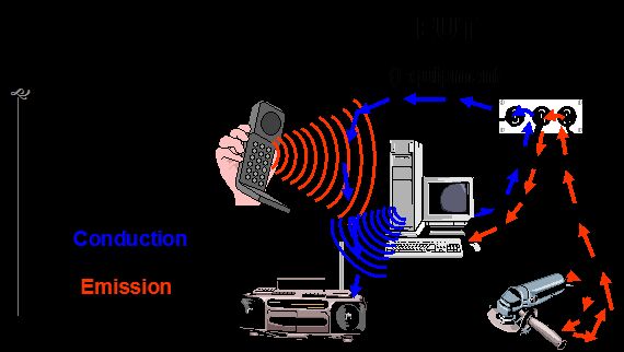
Figure 2: The Schematic of EMC
Introduction of products1. Conducted radiation interference
The RF interference frequency range emitted by this standard covering equipment is 9KHZ-400GHZ. The limits in this standard are determined on a probabilistic basis so that disturbances are suppressed within economically reasonable limits while still achieving adequate levels of radio protection and electromagnetic compatibility. In exceptional cases, additional requirements may be made. The EMI Test System EMI-9KC/EMI-9KB fully meets CISPRl6-1, GB17743, FCC, EN55015 and EN55022.
EMI-9KA/9KB EMI Receiver System is a main test system for EMI (Electro Magnetic Interference) testing.
2. Static Immunity
The International Electrician Commission (IEC) has issued IEC 61000-4-2 version 2.0 (2008-12) entitled “Electromagnetic Compatibility (EMC) – Part 4-2: Test and Measurement Techniques – Electrostatic Discharge Immunity Test”.
This standard covers the immunity requirements and test methods for electrical and electronic equipment subjected to electrostatic discharge, including from equipment to direct operators, from personnel to adjacent objects. In addition, it defines the range of test levels for different environments and different installation conditions, and establishes test procedures. The purpose of this standard is to establish a common and repeatable benchmark for evaluating the performance of electrical and electronic equipment when subjected to electrostatic discharge. It also lists statics that may occur in objects near people and critical equipment, as well as typical waveforms of discharge current, test range, test equipment, test setup, test procedures, calibration procedures, and measurement uncertainty.
The second edition of the standard replaces the first edition published in 1995, and its amendment 1 (1998) and its amendment 2 (2000) together constitute a technical revision that is fully compliant with the basic IEC EMC guidelines 107.
Electrostatic Discharge Simulator (Electrostatic Gun) from LISUN is in full compliance with IEC 61000-4-2, EN61000-4-2, ISO10605, GB/T17626.2, GB/T17215.301 and GB/T17215.322.
3. RF Radiation Immunity
The international standard IEC61000-4-3 was drafted by the 65A subcommittee of the IEC Technical Committee 65 and replaced IEC801-3 published in 1984.
Electromagnetic radiation affects most electronic devices in some way. In addition to intentional electromagnetic energy, some devices generate stray radiation, such as electric welders, thyristor rectifiers, fluorescent lamps, and the like. This interference is manifested in most cases as conducted interference, which is involved in other standards of this series of standards. Methods to prevent the effects of electromagnetic fields often also reduce the effects of such sources of interference.
SDR-2000B Magnetic Shielding Chamber for EMI from LISUN is fully compliant with IEC61000-4-3 and has a suitable size to maintain a uniform field with sufficient space relative to the EUT.
4. Electrical Fast Transient Burst Immunity
The international standard IEC61000-4-4 was developed by the 77B subcommittee of the IEC Technical Committee 77. The purpose of this standard is to evaluate a common reproducible basis for assessing the performance of electrical and electronic equipment’s power supply ports, signals, and control ports in the presence of repetitive fast transients. However, the test of special equipment or systems is not regulated. The repetitive fast transient test is a test that couples a burst of many fast transient pulses to the power ports, signals, and control ports of electrical and electronic equipment. The main points of the test are short rise times of transients, repetition rates and low energy.
EFT61000-4 EFT Immunity Tester from LISUN is developed for the requirements of fast transient burst immunity tests and is the ideal source of interference for EMS measurements.
5. Surge Generator Immunity
The international standard IEC61000-4-5 was developed by the 65th Subcommittee of the IEC Technical Committee 65. This standard has the status of a basic electromagnetic compatibility publication. The immunity requirements for the unipolar surge caused by the switch and lightning transient overvoltage, the test method and the recommended test level range are specified, and several test levels related to different environments and installation conditions are specified.
Automatic Lightning Surge Generator (or Lightning Surge Immunity) SG61000-5 is used to assess the power cord and connect the internal switch stood in line to connect the internal switch to provide a common basis for switching the natural world and lightning caused by the high-energy transient interference performance.
6. RF Conducted Immunity
The international standard IEC61000-4-6 was developed by the 65A subcommittee of the IEC Technical Committee 65 and the 77B subcommittee of the IEC Technical Committee 77. In accordance with IEC Guide 107, it has the status of a basic EMC publication. This standard relates to electrical and electronic equipment requirements for electromagnetic immunity from RF transmitters in the frequency range from 9KHZ to 80MHZ. The device is coupled to the RF field by a cable.
The source of disturbance referred to in this standard usually refers to the electromagnetic field from the RF transmitter. This electromagnetic field may act on the entire cable that connects the mounting equipment. Although the size of the device being harassed is smaller than the wavelength of the disturbance frequency, the output and input lines may become passive receiving antenna networks because their length may be several wavelengths.
The RFCI61000-4-6 RF Conducted Immunity Test System from LISUN is mainly used for conduction sensitivity testing.
7. Power Frequency Magnetic Field Immunity
The international standard IEC61000-4-8 was developed by the 77B subcommittee of the IEC Technical Committee 77. This standard is the eighth part of the fourth part of IEC61000, which has the status of a basic EMC publication in accordance with the IEC107 guidelines. This standard specifies the immunity requirements of equipment under operating conditions for power frequency magnetic field disturbances in the following locations: residential and commercial areas; industrial and mining areas and power plants; medium voltage and high voltage substations. For equipment installed in different locations, the applicability of this standard is determined by the phenomena indicated in Chapter 3. The purpose of this standard is to establish a common and reproducible benchmark to evaluate the performance of electrical, electronic, and electronic equipment used in power frequency magnetic fields. The power frequency magnetic field is generated by the power frequency current in the conductor, or a very small amount is generated by other devices in the vicinity.
PFM61000-8A Magnetic Field Generator from LISUN is a high stability energy test equipment mainly used for electronic product design requirements of immune characteristics and normal frequency magnetic field testing requirements.
8. Voltage Drop Immunity
The international standard IEC/EN61000-4-11 was drafted by the 77B subcommittee of the 177th Technical Committee of the IEC. This standard is Part 11 of Part 4 of IEC61000 and is a basic EMC standard in accordance with IEC Directive 107. This standard specifies the immunity test method and preferred test level range for voltage sag, short interruption and voltage change of electrical and electronic equipment connected to the low voltage power supply network. This standard applies to electrical and electronic equipment with a rated input current of no more than 16A per phase. The purpose of this standard is to establish a general guideline for evaluating the immunity of electrical and electronic equipment to voltage dips, short interruptions and voltage changes.
CSS61000-11 Voltage Dip and Interruptions Generator from LISUN is a highly reliable device specially designed for the characteristics and requirements of voltage dip and short-term interrupt immunity test.
Lisun Instruments Limited was found by LISUN GROUP in 2003. LISUN quality system has been strictly certified by ISO9001:2015. As a CIE Membership, LISUN products are designed based on CIE, IEC and other international or national standards. All products passed CE certificate and authenticated by the third party lab.
Our main products are Goniophotometer, Spectroradiometer, Integrating Sphere, LED Test Instruments, CFL Test Instruments, Photometer and Colorimeter, EMC & EMI Testing, Surge Generator, Electrical Safety Testing, Environmental Test Chamber, Waterproof Test , Dustproof Test Chamber, High and Low temperature Humidity Chamber, Plug and Switch Testing, AC and DC Power Supply.
Please feel free to contact us if you need any support.
Tech Dep: Service@Lisungroup.com, Cell/WhatsApp: +8615317907381
Sales Dep: Sales@Lisungroup.com, Cell/WhatsApp: +8618917996096
The Methods and Principles for LED Lighting EFT Immunity Measurement According to IEC 61000-4-4
When doing IEC 61000-4-4 EFT immunity test, there are L1, L2, L3, N and PE interface. PE and earth are two different concepts. Electrical fast pulse interference is common mode, in the experimental setup figure of the standard, we can see the signal cable which is from the test generator can connect with corresponding power lines (L1, L2, L3 , N and PE) through the selectable coupling capacitor, and the signal cable shield connects with the chassis of coupling/decoupling network, and the chassis is connected to the reference ground terminal.
This indicates that burst interference is actually applied between the power line and the reference earth, so the interference which is added on the power line is common mode interference, and for the experimental method of using coupled folder, the electrical fast pulse will be added into the tested cable through the distributed capacitance which is between coupling plate and the tested cable. But the pulse which tested cable received is still relatively to the reference ground plane.
Thus, the interference applied on the tested cable by coupling clamp is still common mode. After confirming the nature of the interference, we can take the appropriate measures to make the equipment passed the test. So we can see, the X capacitor (differential mode capacitor) which used in power filters cannot inhibit EFT interference.
If the device included metal shell, the Y capacitors (common mode capacitance) will work. We can bypass the high frequency EFT to the shell, and then back to the signal source via the distributed capacitance which between the device shell and the reference ground, so as not to enter the circuit.
The mechanism of electrical fast pulse interference causes equipment failed, according to foreign scholars’ research, the single pulse energy is small, it will not cause malfunction of the equipment. However, the interference signal of burst charges apparatus line junction capacitance, when the above energy accumulated to a certain extent, it is possible to cause malfunction of the power line (as well as the system).
Therefore, there will be a time process for the line error, and there will be some chance (cannot guarantee the time interval of the error, especially when the tested voltage reaches the critical point). And it is difficult to judge whether the device is more likely to fail for separately applying a single pulse or applying pulse group together. And it is hard to say whether the device is more sensitive for positive pulses or negative pulses.
Practice shows that one device is usually particularly sensitive to a polarity of a power cable under a certain kind of tested voltage. Experiments show that the signal line is much more sensitive than the power line for the electrical fast pulse interference.
Effective measures for equipment passing the electrical fast pulse test. First we analyze the methods of interference injection: EFT interference signal is coupling to the main power lines by coupling the 33nF capacitance of decoupling network (and the signal or control cables applies interference through capacitive coupling clamp, the equivalent capacitance is 100pF). For 33nF capacitance, it’s cutoff frequency is 100K, which means
The interference signal which is more than 100KHZ can be passed; but for 100pF capacitance, the cut-off frequency is 30M, only allows interference whose frequency is more than 30MHz passed. The interference waveform of the electrical fast pulse is 5ns / 50ns, repetition frequency is 5K, pulse duration is 15ms, burst repetition period is 300ms. According to the Fourier transform, its spectrum is from 5K to 100M discrete spectral lines, and the distance between each spectral line is the pulse repetition frequency.
After the above, we can know that the coupling capacitance which applies the interference plays a role of a high-pass filter, because the impedance of the capacitance decreases as the frequency increases, the low-frequency in the interference will not be coupled to the EUT, only the interference signal with higher frequencies will enter the EUT. When we add the common mode inductance into the EUT circuit (with particular attention to that, the common mode inductance must be added to the main power line and its return line or it will reach saturation and thus cannot reach the purpose of attenuating interference), it will attenuate some of the high frequency interference, because the impedance of the capacitance increases as frequency increases. Therefore, the interference signal which actually applied to EUT only left the intermediate frequency.
Lisun Instruments Limited was found by LISUN GROUP in 2003. LISUN quality system has been strictly certified by ISO9001:2015. As a CIE Membership, LISUN products are designed based on CIE, IEC and other international or national standards. All products passed CE certificate and authenticated by the third party lab.
Our main products are Goniophotometer, Spectroradiometer, Integrating Sphere, LED Test Instruments, CFL Test Instruments, Photometer and Colorimeter, EMC & EMI Testing, Surge Generator, Electrical Safety Testing, Environmental Test Chamber, Waterproof Test , Dustproof Test Chamber, High and Low temperature Humidity Chamber, Plug and Switch Testing, AC and DC Power Supply.
Please feel free to contact us if you need any support.
Tech Dep: Service@Lisungroup.com, Cell/WhatsApp: +8615317907381
Sales Dep: Sales@Lisungroup.com, Cell/WhatsApp: +8618917996096
Tuesday, May 12, 2020
The LED Driver RMS Value Measurement and Analysis
As we known the quality of LED lighting products depend on two points: One is LED chip(light source); Second is LED power driver. In the practice, there only have few company can provide qualified LED chip such as PHILIPS, OSRAM and CREE in the market. Generally, the LED chip have very small change to get quality problem, but we heard many news about low quality LED lighting products was found and caused big losses to customers because of un-qualified LED driver. As considering the importance of LED driver, this article will discuss some technical introduction and measurement technology.
There have some necessary test items of LED Power Driver Tester such as Crest Factor, Effective Power, Reactive Power, Apparent Power, Power Factor, Voltage/Current (RMS value, Average value) and THD harmonic parameters etc. In the practice measurement, lots of people found it have big difference between get from LED driver tester and multimeter, and this difference focus on Voltage/current rms, apparent power, power factor, RMS(rms) and average. Many users feedback the voltage/current(RMS date) from multimeter is lower or bigger than LED driver tester, it is necessary to make a explain here that the values from LED driver tester are RMS(true and effective value), the average curren we often talking is also RMS(average value), the average current only can get when it satrt test and it is RMS average value during start process; the software data is keep some with front panel of LED driver tester. In the meantime, according to international standards, the RMS(true and effective value) is needed only when test LED driver, it is meaningless to measure average value. The LED driver tester will show voltage, current and power, but the power is not equal of voltage multiply current; the voltage multiply current directly get inspecting power, the LED driver tester showed value is active power. If only use multimeter to measure average value, then there is no need use professional LED driver tester. According to IEC 62384 standard, the Voltage True RMS (Vrms), True RMS Current (rms), Active Power (P) and Power Factor (PF) calculate way as below:
In the above formula, “N” is stand the number of sampled points during the period (the period depends on the frequency of the signal to be measured) and the value at a certain sampling time. The LED driver tester provides two test methods to calculate the total harmonic distortion (THD), namely IEC and CSA, respectively:
In the above two formulas:
THD: Represents the relative value of voltage/current total harmonic distortion
C:Represents the K times harmonic effective value of the voltage or current
K:Number of harmonics
N:The maximum harmonic frequency (This LED driver tester is 50)
C:RMS value of fundamental voltage or current (ie, 1 harmonic)
In the practice measurement, when use RMS value or average value of LED constant output current to judge quality of LED driver, there have two ideas in the market: some use RMS value but some use average. Caused this two difference idea due to LED driver have big current ripple and each LED driver is different, then the RMS value and average value of output current have big difference, but according to the actual situation and standards, the only judge factor is focus on RMS value, we can refer average value but can's see it as key judge factor.
Lisun Instruments Limited was found by LISUN GROUP in 2003. LISUN quality system has been strictly certified by ISO9001:2015. As a CIE Membership, LISUN products are designed based on CIE, IEC and other international or national standards. All products passed CE certificate and authenticated by the third party lab.
Our main products are Goniophotometer, Spectroradiometer, Integrating Sphere, LED Test Instruments, CFL Test Instruments, Photometer and Colorimeter, EMC & EMI Testing, Surge Generator, Electrical Safety Testing, Environmental Test Chamber, Waterproof Test , Dustproof Test Chamber, High and Low temperature Humidity Chamber, Plug and Switch Testing, AC and DC Power Supply.
Please feel free to contact us if you need any support.
Tech Dep: Service@Lisungroup.com, Cell/WhatsApp: +8615317907381
Sales Dep: Sales@Lisungroup.com, Cell/WhatsApp: +8618917996096
Thursday, May 7, 2020
How do you choose integrating sphere if you test small size but high power HID lamp?
HID lamp is high intensity discharge lamp. High pressure sodium lamp, high pressure mercury lamp, xenon lamp, metal halide lamp are all belong to HID lamp.
We generally use Integrating Sphere Spectroradiometer Test System to test the photometric, colorimetric and electrometric parameters. Generally we suggest the diameter size of Integrating Sphere according to the size of lamp under test. If you test single LED or LED chips, we recommend small integrating sphere such as IS-0.3M or IS-0.5M. 1.2m luminaries should at least use D=1.5M integrating sphere to measure.
If you test high power small size HID lamp, how do we choose Integrating Sphere? If the power of HID lamp is over 200W, we generally recommend use D=2.0m integrating sphere, we will not suggest small integrating sphere because of these reasons:
Lisun Instruments Limited was found by LISUN GROUP in 2003. LISUN quality system has been strictly certified by ISO9001:2015. As a CIE Membership, LISUN products are designed based on CIE, IEC and other international or national standards. All products passed CE certificate and authenticated by the third party lab.
Our main products are Goniophotometer, Spectroradiometer, Integrating Sphere, LED Test Instruments, CFL Test Instruments, Photometer and Colorimeter, EMC & EMI Testing, Surge Generator, Electrical Safety Testing, Environmental Test Chamber, Waterproof Test , Dustproof Test Chamber, High and Low temperature Humidity Chamber, Plug and Switch Testing, AC and DC Power Supply.
Please feel free to contact us if you need any support.
Tech Dep: Service@Lisungroup.com, Cell/WhatsApp: +8615317907381
Sales Dep: Sales@Lisungroup.com, Cell/WhatsApp: +8618917996096
HID lamp is high intensity discharge lamp. High pressure sodium lamp, high pressure mercury lamp, xenon lamp, metal halide lamp are all belong to HID lamp.
We generally use Integrating Sphere Spectroradiometer Test System to test the photometric, colorimetric and electrometric parameters. Generally we suggest the diameter size of Integrating Sphere according to the size of lamp under test. If you test single LED or LED chips, we recommend small integrating sphere such as IS-0.3M or IS-0.5M. 1.2m luminaries should at least use D=1.5M integrating sphere to measure.
If you test high power small size HID lamp, how do we choose Integrating Sphere? If the power of HID lamp is over 200W, we generally recommend use D=2.0m integrating sphere, we will not suggest small integrating sphere because of these reasons:
- If integrating sphere is too small, cooling is not good, the temperature of integrating sphere will affect the test result.
- The signal will be too strong, the integration time will be very shot and the test error for lumen will increase.
Lisun Instruments Limited was found by LISUN GROUP in 2003. LISUN quality system has been strictly certified by ISO9001:2015. As a CIE Membership, LISUN products are designed based on CIE, IEC and other international or national standards. All products passed CE certificate and authenticated by the third party lab.
Our main products are Goniophotometer, Spectroradiometer, Integrating Sphere, LED Test Instruments, CFL Test Instruments, Photometer and Colorimeter, EMC & EMI Testing, Surge Generator, Electrical Safety Testing, Environmental Test Chamber, Waterproof Test , Dustproof Test Chamber, High and Low temperature Humidity Chamber, Plug and Switch Testing, AC and DC Power Supply.
Please feel free to contact us if you need any support.
Tech Dep: Service@Lisungroup.com, Cell/WhatsApp: +8615317907381
Sales Dep: Sales@Lisungroup.com, Cell/WhatsApp: +8618917996096
Subscribe to:
Posts (Atom)