LED package is mainly to provide a platform for LED chips, so that LED chips have better performance of light, electricity and heat. Good packaging can make LEDs have better luminous efficiency and good heat dissipation environment, and good heat dissipation environment can enhance LEDs. The service life. LED packaging technology is mainly built on five main considerations, namely optical extraction efficiency, thermal resistance, power dissipation, reliability and cost performance (Lm/$).
There are many kinds of LED chip packages, and different styles of packages should be used according to the actual photoelectric characteristics. However, the common LED packages have the following five common patterns.
First, the LED chip soft package, this package style is generally used in the LED display of character display, digital display, and electric display. The soft package of the LED chip is to directly bond the LED chip on the PCB printing plate, and connect the desired characters and display effects through the welding wire. These chips and wire bonds are then protected with a transparent resin.
Second, the pin packing method. The main advantage of this kind of package is that it can flexibly control the angle of light emitted by the LED chip, and it can also easily realize the function of measuring light. The pin package method only needs to fix the chip on the lead frame and then encapsulate it with epoxy resin. Can be a single LED device.
Lisun Instruments Limited was found by LISUN GROUP in 2003. LISUN quality system has been strictly certified by ISO9001:2015. As a CIE Membership, LISUN products are designed based on CIE, IEC and other international or national standards. All products passed CE certificate and authenticated by the third party lab.
Our main products are Goniophotometer, Spectroradiometer, Integrating Sphere, LED Test Instruments, CFL Test Instruments, Photometer and Colorimeter, EMC & EMI Testing, Surge Generator, Electrical Safety Testing, Environmental Test Chamber, Waterproof Test , Dustproof Test Chamber, High and Low temperature Humidity Chamber, Plug and Switch Testing, AC and DC Power Supply.
Please feel free to contact us if you need any support.
Tech Dep: Service@Lisungroup.com, Cell/WhatsApp:+8615317907381
Sales Dep: Sales@Lisungroup.com, Cell/WhatsApp:+8618917996096
Thursday, February 27, 2020
LED Lamps Aging and Life Test
Many customers need aging LED lamps, but do not have a clear concept of aging test and life test.
Aging test usually use aging test racks. What is aging test rack? Aging rack is dedicated to simulate the products in real conditions involved in the use of various factors on the aging of the product conditions to strengthen the process of the corresponding conditions.
Why we need aging test? Electronic products, no matter components, parts or machines, all need aging test. Aging and test is not one concept, aging firstly and then test. Electronic product after manufacturing forms a complete product, which is able to play its role. But users may find a variety of problems after use, most problems occurs in the first few hours to dozens of hours. Later, formulate electronic products aging and test to simulate the using state or equivalent products. This process is done by the product manufacturer.
The problem products will stay in factory, products without problems will sell to users, to ensure that the products that users buy are reliable or less problematic, which is the meaning of aging test.
LED life and reliability of LED products is one of the most important performances. Life is the ultimate performance of reliability, but the theoretical life of LED is very long, according to the use of different conditions and drive current, LED life has 50.000 hours or more. Different with the traditional light source, LED will not go out instantly, but decays slowly. According to LM-80, LED light source should operate at the lowest temperature of the three case temperatures (Ts) for the photometric test and should use the same drive current. These three case temperatures should be 55℃, 85℃ and a third temperature provided by the DUT manufacturer. The case temperature provided by the DUT manufacturer and drive current should meet the customers’ requirements and are within the recommended operating temperature range. Test unit should be driven for at least 6000 hours and the data collected at least every 1000 hours.
Rated Lumen Maintenance Life is the elapsed operating time over which the LED light source will maintain the percentage of its initial light output. The lumen maintenance rate is a contradiction of the flux attenuation.
Lisun LEDLM-80PL LED Lumen Maintenance and Aging Life Test System is designed according to standards of IES-LM-80, IES-LM-82, TM-21 and GB2312-80.
Wednesday, February 26, 2020
ISO 17025: Accreditation Criteria for the Competence of Testing and Calibration Laboratories
ISO 17025 is the international standard for laboratory accreditation services; the latest version is released in May, 2005. The full name of ISO/IEC 17025:2005-5-15 is Accreditation Criteria for the Competence of Testing and Calibration Laboratories. ISO17025 standard is the laboratory management standard formulated by the international Standardization Organization ISO/CASCO (Conformity Assessment Committee). Internationally the organization that manages laboratory accreditation is International Laboratory Accreditation Cooperation (ILAC), attended by 44 laboratory accreditation institute including CHINA NATIONAL ACCREDITATION COMMITTEE FOR LABORATORIES (CNACL).
Standard mainly includes: definitions, organization and management, quality system, audits and reviews, personnel, accommodation and environmental conditions, equipment and reference materials, traceability and calibration, calibration and test methods, sample management, record, certificate and report, subcontracting tests and calibrations, purchasing services and suppliers, complaints etc. This standard core content is equipment and reference materials, traceability and calibration, calibration and test methods and sample management; these contact emphasis is to assess whether the laboratory or test capability meets the expected requirements.
CHINA NATIONAL ACCREDITATION SERVICE FOR CONFORMITY ASSESSMENT (CNAS) laboratory accreditation criteria are according to ISO/IEC 17025, it is an internationally accepted standard for laboratory quality and technical requirements. The laboratory gets accredited by CNAS, which means that it has been established a set of quality management system based on international standards. As long as the personnel carry out work according to the system strictly, the laboratory’s technical capacity will be guaranteed. The test/calibration services provided by the laboratory to the customer can claim to be accordance with the international standards.
CNAS is the only laboratory accreditation institute in China; it bears nationwide laboratories for ISO17025 standard approval. All calibration and test laboratories can adopt and implement the ISO 17025 standard. In accordance with international practice, data provided by the ISO17025 standard laboratory have legal effect and get international recognized. At present, China has more than 1,000 laboratories that get through the ISO17025 standard certification. Through the implementation of standard to improve the accuracy of the test data and results and expand the laboratory’s reputation, thereby greatly improve the economic and social benefits.
All Lisun products can be sent to CNAS laboratory to do calibration and get CNAS calibration certificate, which meets ISO17025 standard.
Lisun Instruments Limited was found by LISUN GROUP in 2003. LISUN quality system has been strictly certified by ISO9001:2015. As a CIE Membership, LISUN products are designed based on CIE, IEC and other international or national standards. All products passed CE certificate and authenticated by the third party lab.
Our main products are Goniophotometer, Spectroradiometer, Integrating Sphere, LED Test Instruments, CFL Test Instruments, Photometer and Colorimeter, EMC & EMI Testing, Surge Generator, Electrical Safety Testing, Environmental Test Chamber, Waterproof Test , Dustproof Test Chamber, High and Low temperature Humidity Chamber, Plug and Switch Testing, AC and DC Power Supply.
Please feel free to contact us if you need any support.
Tech Dep: Service@Lisungroup.com, Cell/WhatsApp:+8615317907381
Sales Dep: Sales@Lisungroup.com, Cell/WhatsApp:+8618917996096
IP Level Test Introduction
IP is the abbreviation of Ingress Protection. IP grade is the protection level for electrical equipment shell against the foreign body intrusion. It comes from the international electrical commission standard IEC 60529 which was also used as the national
standard of America in 2004. In this standard, for the protection level of electrical equipment shell against the foreign body intrusion, the IP level format is IPXX. In which the XX are the two Arabia number. The first tag number indicates the protection level of contact protection and external object protection; the second tag number indicates the protection level of waterproof. For the more specific protection level can refer to the table below.
Level of protection usually uses IP with the following two figures to express. The numbers used to specify the protection level. The first number indicates the range of the device against dust, or the extent of people against damage in sealed environment. ‘ I ‘ represents the level of prevention of the entry of solid foreign bodies, and the highest level is 6; the second number indicates the level of the device against water. P representative the level prevent from water, the highest level is 8. Such as the protection level of motor IP65, IP55 and so on.
Dustproof Level
Waterproof Level
(1) IPX 1
Method name: Vertical drop test
Test equipment: Drop test device
Sample placement: According to the normal working position of the sample, place the sample on the rotating sample table of 1r/min. The distance between the top of the sample and the drop mouth is no more than 200mm
Test condition: Drip rate is 10.05 mm/min
Duration: 10 min
(2) IPX 2
Method name: Inclined 15 degree drop test
Test equipment: Drop test device
Sample placement: Making a 15° angle between the sample surface and the vertical line. The distance between sample top to drip mouth no greater than 200mm. After each test, change to the other side, a total of four times.
Test condition: Drip volume is 30.5 mm/min
Duration: 4 x 2.5 min (total 10 min)
(3) IPX 3
Method name: water spray test
Test method:
Sample placement: Select the appropriate radius of the tube so that the sample table height is in the position of the diameter of the pipe diameter. Place the sample on the sample table to make the distance between the top of the sample is no more than 200mm, and the sample table is not rotated.
Experimental conditions: Water volume calculated according to the number of holes in the pipe, each hole is 0.07 L/min. When pouring water, the spray hole which placed in the both sides of the swing pipe would spray to the sample. The sample placed in the pipe center circle. The swing pipe would swing 60° twice on both sides of the vertical of 60 degrees, total 120°. Each swing (2 x 120) is about 4s
Test time: Continuous pouring water 10 min
Sample placement: Make the parallel distance between the top of the test and the head of the hand-held nozzle is 300mm to 500mm
Test condition: When the test should be installed with the balance of the baffle, the water flow is 10 L/min
Test time: According to the sample shell surface area calculated, per square meter is 1 min (not including the installation area), at least 5 min
(4) IPX 4
Name: splashing test method
Test method:
Test conditions: In addition to the conditions following, all the same and the above IPX 3 a models are the same; the water spray area is placed in the middle of the tube at the same time, the 90 degrees of the water spray nozzle. The sample is placed in the pipe center circle. The vertical pipe swing of 180° on both sides, total about 360 degrees. Each swing (2 x 360) is about 12s
Test time: Same as the above IPX 3 a models(that is, 10 min).
Test conditions: Installation of the device on the installation of a balanced weight of the baffle, and the rest of the above IPX 3 b;
Test time: Same as the above IPX 3 b models, that is, the sample of the shell surface area per square meter is 1 min (not including the installation area) at least 5min
(5) IPX 5
Method name: Spray test
Test equipment: The nozzle diameter of the nozzle is 6.3mm
Test condition: The water flow rate is 2.5m (750 L/min), the water flow rate is 12.5 3M (L/h).
Test time: According to the sample shell surface area calculation, per square meter is 1 min (not including the installation area) at least 3 min
(6) IPX 6
Method name: Strong water spray test;
Test equipment: Nozzle diameter of 12.5 mm
Test conditions: 100 L/min (6000 L/h)
Test time: According to the sample shell surface area calculation, per square meter is 1 min (not including the installation area) at least 3 min
(7) IPX 7
Method name: Short-time immersion test
Test equipment and test conditions: Immersion tank. The sample size should be put into the immersion tank, and the distance between the bottom of the sample and the surface of the sample is at least 1m. The top of the sample is at least 0.15m
Test time: 30 min
(8) IPX 8
Method name: continuous dive test;
Test equipment, test conditions and test time: Decided by the supply and demand (sell and buy). Its severity degree is higher than IPX 7.
Note: In addition, many outdoor electronic products also stress the ability to float.
Lisun developed JL-X waterproof test system and SC series of dust test box fully meet the IEC 60529. Lisun Electronic (Shanghai) office is committed to the development and after-sales maintenance of lighting instrument, EMI / EMC testing system and safety testing instruments in the domestic and global market. The full range of products of Lisun are in strict accordance with the quality management and control of ISO9001:2008 requirements for R & D and production; Lisun is also the member unit of global lighting CIE association, all products are according to CIE requirements; in addition, all products of Lisun are certified by CE and get the qualification of the EU.
standard of America in 2004. In this standard, for the protection level of electrical equipment shell against the foreign body intrusion, the IP level format is IPXX. In which the XX are the two Arabia number. The first tag number indicates the protection level of contact protection and external object protection; the second tag number indicates the protection level of waterproof. For the more specific protection level can refer to the table below.
Level of protection usually uses IP with the following two figures to express. The numbers used to specify the protection level. The first number indicates the range of the device against dust, or the extent of people against damage in sealed environment. ‘ I ‘ represents the level of prevention of the entry of solid foreign bodies, and the highest level is 6; the second number indicates the level of the device against water. P representative the level prevent from water, the highest level is 8. Such as the protection level of motor IP65, IP55 and so on.
Dustproof Level
| Number | Protection Level | Definition |
| 0 | No protection | No special protection |
| 1 | Prevent objects from more than 50mm | Prevent the human body from accidentally touch the internal parts of the lamp, prevent the object intrusion which diameter is greater than 50mm |
| 2 |
Prevent objects from more than 12mm | Prevent the finger from the internal parts of the lamp |
| 3 | Prevent objects from more than 2.5mm | Prevent the object, tool, wire intrusion which diameter is greater than 2.5mm |
| 4 |
Prevent objects from more than 1.0mm | Prevent the mosquitoes, insects or objects intrusion which diameter of more than 1.0mm |
| 5 |
Dustproof |
Can not completely prevent dust intrusion, but the amount of intrusion of dust will not affect the normal operation of electrical |
| 6 | Dustproof | Completely prevent dust intrusion |
| Number | Protection Level | Definition |
| 0 | No protection | No special protection |
| 1 | Prevent water dripping | Prevent vertical drop of water |
| 2 | Prevent dripping water intrusion even when inclined 15 degrees | Can still prevent dripping when the lamp is inclined 15 degrees, |
| 3 | Prevent the injection of water intrusion | Prevent rain, or vertical to the angle is less than 50 degrees in the direction of the water jet |
| 4 |
Prevent splashing water intrusion | Prevent water from splashing in all directions |
| 5 |
Prevent the ingress of water waves | Prevent the waves or spray holes rapidly sprayed water from intrusion |
| 6 |
Prevent the ingress of water waves |
Lamps and lanterns can still ensure the normal operation when into the water in a certain time or water pressure conditions, |
| 7 |
Prevent water from immersing into the lamp | The lamp has no time limit for the submerged water under the condition of a certain water pressure, and can ensure the normal operation |
| 8 | Prevent the sinking | Prevent the sinking |
(1) IPX 1
Method name: Vertical drop test
Test equipment: Drop test device
Sample placement: According to the normal working position of the sample, place the sample on the rotating sample table of 1r/min. The distance between the top of the sample and the drop mouth is no more than 200mm
Test condition: Drip rate is 10.05 mm/min
Duration: 10 min
(2) IPX 2
Method name: Inclined 15 degree drop test
Test equipment: Drop test device
Sample placement: Making a 15° angle between the sample surface and the vertical line. The distance between sample top to drip mouth no greater than 200mm. After each test, change to the other side, a total of four times.
Test condition: Drip volume is 30.5 mm/min
Duration: 4 x 2.5 min (total 10 min)
(3) IPX 3
Method name: water spray test
Test method:
- Swing Tube type spray test
Sample placement: Select the appropriate radius of the tube so that the sample table height is in the position of the diameter of the pipe diameter. Place the sample on the sample table to make the distance between the top of the sample is no more than 200mm, and the sample table is not rotated.
Experimental conditions: Water volume calculated according to the number of holes in the pipe, each hole is 0.07 L/min. When pouring water, the spray hole which placed in the both sides of the swing pipe would spray to the sample. The sample placed in the pipe center circle. The swing pipe would swing 60° twice on both sides of the vertical of 60 degrees, total 120°. Each swing (2 x 120) is about 4s
Test time: Continuous pouring water 10 min
- Shower nozzle type shower water test
Sample placement: Make the parallel distance between the top of the test and the head of the hand-held nozzle is 300mm to 500mm
Test condition: When the test should be installed with the balance of the baffle, the water flow is 10 L/min
Test time: According to the sample shell surface area calculated, per square meter is 1 min (not including the installation area), at least 5 min
(4) IPX 4
Name: splashing test method
Test method:
- Swing pipe type splashing test
Test conditions: In addition to the conditions following, all the same and the above IPX 3 a models are the same; the water spray area is placed in the middle of the tube at the same time, the 90 degrees of the water spray nozzle. The sample is placed in the pipe center circle. The vertical pipe swing of 180° on both sides, total about 360 degrees. Each swing (2 x 360) is about 12s
Test time: Same as the above IPX 3 a models(that is, 10 min).
- Nozzle type splashing test
Test conditions: Installation of the device on the installation of a balanced weight of the baffle, and the rest of the above IPX 3 b;
Test time: Same as the above IPX 3 b models, that is, the sample of the shell surface area per square meter is 1 min (not including the installation area) at least 5min
(5) IPX 5
Method name: Spray test
Test equipment: The nozzle diameter of the nozzle is 6.3mm
Test condition: The water flow rate is 2.5m (750 L/min), the water flow rate is 12.5 3M (L/h).
Test time: According to the sample shell surface area calculation, per square meter is 1 min (not including the installation area) at least 3 min
(6) IPX 6
Method name: Strong water spray test;
Test equipment: Nozzle diameter of 12.5 mm
Test conditions: 100 L/min (6000 L/h)
Test time: According to the sample shell surface area calculation, per square meter is 1 min (not including the installation area) at least 3 min
(7) IPX 7
Method name: Short-time immersion test
Test equipment and test conditions: Immersion tank. The sample size should be put into the immersion tank, and the distance between the bottom of the sample and the surface of the sample is at least 1m. The top of the sample is at least 0.15m
Test time: 30 min
(8) IPX 8
Method name: continuous dive test;
Test equipment, test conditions and test time: Decided by the supply and demand (sell and buy). Its severity degree is higher than IPX 7.
Note: In addition, many outdoor electronic products also stress the ability to float.
Lisun developed JL-X waterproof test system and SC series of dust test box fully meet the IEC 60529. Lisun Electronic (Shanghai) office is committed to the development and after-sales maintenance of lighting instrument, EMI / EMC testing system and safety testing instruments in the domestic and global market. The full range of products of Lisun are in strict accordance with the quality management and control of ISO9001:2008 requirements for R & D and production; Lisun is also the member unit of global lighting CIE association, all products are according to CIE requirements; in addition, all products of Lisun are certified by CE and get the qualification of the EU.
Tuesday, February 25, 2020
Introduction of Conducted Immunity Testing
This page is a brief introduction and description for conducted immunity testing which based on IEC 61000-4-4 fast transient burst test, IEC 61000-4-5 lightning surge test, IEC 61000-4-11 voltage cycle drop test and IEC 61000-4-12 ring wave test.
IEC 61000-4-4 establishes a common and reproducible reference for evaluating the immunity of electrical and electronic equipment when subjected to electrical fast transient/bursts on supply, signal, control and earth ports. The test method documented in this part of IEC 61000 describes a consistent method to assess the immunity of an equipment or system against a defined phenomenon.
IEC 61000-4-5 relates to the immunity requirements, test methods, and range of recommended test levels for equipment to unidirectional surges caused by over-voltages from switching and lightning transients. Several test levels are defined which relate to different environment and installation conditions. These requirements are developed for and are applicable to electrical and electronic equipment. The object of this standard is to establish a common reference for evaluating the immunity of electrical and electronic equipment when subjected to surges.
IEC 61000-4-11 defines the immunity test methods and range of preferred test levels for electrical and electronic equipment connected to low-voltage power supply networks for voltage dips, short interruptions, and voltage variations. This standard applies to electrical and electronic equipment having a rated input current not exceeding 16 A per phase, for connection to 50 Hz or 60 Hz A.C. networks. It does not apply to electrical and electronic equipment for connection to 400 Hz A.C. networks.
IEC 61000-4-12 relates to the immunity requirements and test methods for electrical and electronic equipment, under operational conditions, to non-repetitive damped oscillatory transients (ring waves) occurring in low-voltage power, control and signal lines supplied by public and non-public networks. The object of this basic standard is to establish the immunity requirements and a common reference for evaluating in a laboratory the performance of electrical and electronic equipment intended for residential, commercial and industrial applications, as well as of equipment intended for power stations and substations, as applicable.
Lisun Instruments Limited was found by LISUN GROUP in 2003. LISUN quality system has been strictly certified by ISO9001:2015. As a CIE Membership, LISUN products are designed based on CIE, IEC and other international or national standards. All products passed CE certificate and authenticated by the third party lab.
Our main products are Goniophotometer, Spectroradiometer, Integrating Sphere, LED Test Instruments, CFL Test Instruments, Photometer and Colorimeter, EMC & EMI Testing, Surge Generator, Electrical Safety Testing, Environmental Test Chamber, Waterproof Test , Dustproof Test Chamber, High and Low temperature Humidity Chamber, Plug and Switch Testing, AC and DC Power Supply.
Please feel free to contact us if you need any support.
Tech Dep: Service@Lisungroup.com, Cell/WhatsApp:+8615317907381
Sales Dep: Sales@Lisungroup.com, Cell/WhatsApp:+8618917996096
Interpretation of the latest American Energy Star IES LM-79-19 standard
Spanish version LM-79-19 download: ANSI/IES LM-79-19 Mediciones Fotométricas y Eléctricas de Productos de Iluminación de Estado Sólido (SSL)
ANSI (American National Standards Institute) and IES(Illuminating Engineering Society of North America) officially released the latest version of the IES LM-79-19 standard in May 2019, it will replace the LM-79-08 version. LISUN interpreted the new standard as follows:
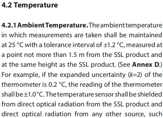
1. Test Environment (4.2.1 / 4.3 / 4.7 on Page 2 / Page 3 / Page 4 of the standard)
1.1 Ambient Temperature:25℃±1.2℃
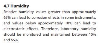
1.2 Humidity: 10%-65%
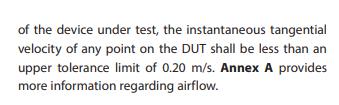
1.3 Airflow: 0.2m/s
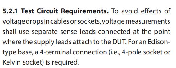
2. Test Circuit Requirements (5.2.1 on Page 4 of the standard): Power supply request4-terminal connection, 2- terminal power supply, 2- terminal feedback
3. AC Power Supply (5.1.2 on page 4 of the standard)
3.1 Load regulation rate: ±0.2%
3.2 Accuracy requirements: 0.1% (reading) + 0.1% (range)
3.3 Example: If the power supply of lamp is 220V and the range is 300V, the actual output voltage should be 220V ± 0.26V
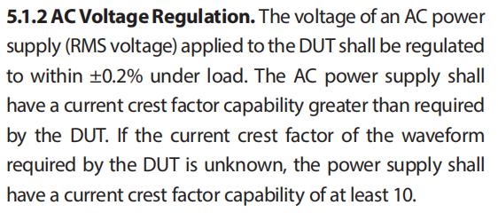
LISUN LSP-500VAR Pure Sine Wave AC Power Source fully meet the requirement, click here to learn more about it.
4. DC Power Supply (5.1.3 on Page 4 of the standard)
4.1 Load regulation rate: ±0.2%
4.2 Accuracy requirements: Current and voltage are both 0.1%
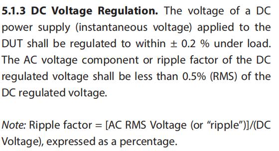
LISUN DC3010 Digital CC and CV DC Power Supply fully meet the requirement, click here to learn more about it.
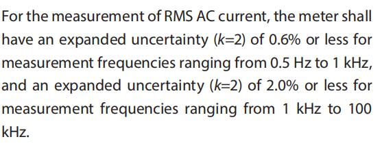
5. AC Power Meters (5.3.2 on Page 5 of the Standard, 5.3.4 on Page 5 of the Standard)
5.1 Sampling frequency : 1kHz-100kHz
5.2 The meter shall have an expanded uncertainty (k=2) of 0.6% or less for measurement frequencies ranging from 0.5Hz to 1kHz, and an expanded unvertainty (k=2) of 2.0% or less for measurement frequencies ranging from 1kHz to 100kHz
5.3 Total Harmonic Distortion Measurement 2~50 times
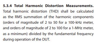
LISUN LS2050 Digital Power Meter fully meet the requirement. Click here to learn more about it.
6. Photometric probe (7.3.2 on Page 9 of the Standard)
6.1 Cosine angular responsivity f2(ε,φ) less than 2%
6.2 f1’ less than 3%
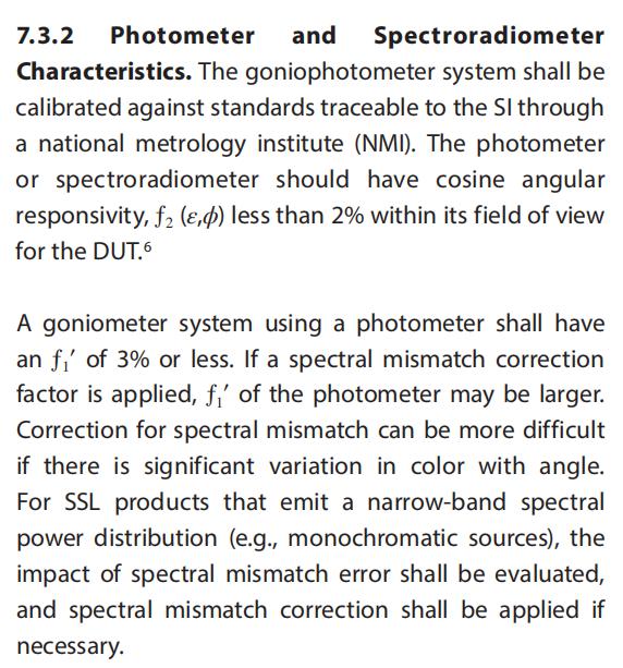
7. Spectroradiometer (7.3.2 on Page 9 of standard)
7.1 380-780nm
7.2 Bandwidth not greater than 5nm
7.3 Wevelength unvertainty within 0.5nm
7.4 Sensitivity: Refer to LM-78-17 (7.2 on Page 7 of standard)
LISUN LPCE-2 High Precision Spectroradiometer Integrating Sphere System fully meet the requierment, click here to learn more about it.
LPCE-2(LMS 9000) Spectrophotometer & Integrating Sphere Test System
8. Goniometer variable angle tester (7.3.3 on Page 9 of standard)
8.1 For lamps with beam angle < 20°: 100%-50% maximum luminous intensity choose no more than 1 degree angular resolution; 50%-10% maximum luminous intensity choose no more than 2 degrees angular resolution; 10%-0% maximum luminous intensity choose no more than 5 degrees angular resolution;
8.2 For lamps with beam angle ≥20°: 100%-50% maximum luminous intensity choose no more than 2 degrees angular resolution; 50%-0% maximum luminous intensity choose no more than 5 degrees angular resolution。
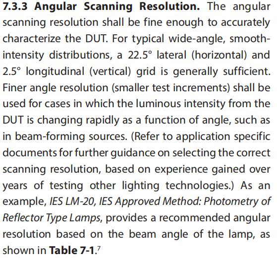
LISUN LSG-5000CCD Moving Detector Goniospectroradiometer fully meet the requierment, click here to learn more about it.

LSG-5000CCD Moving Detector Goniospectroradiometer
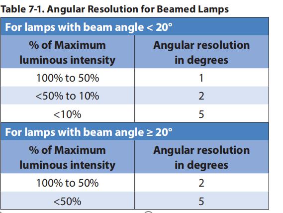
9. Stabilization Requirement (6.4 on Page 7 of standard)
9.1 Monitor for at least 30 minutes
9.2 Take at least three readings of the light output and electrical power consumption taken over period of 20 minutes
9.3 Stability shall be achieved when the variation (maximum to minimum) divided by the last measurements is less than 0.5%
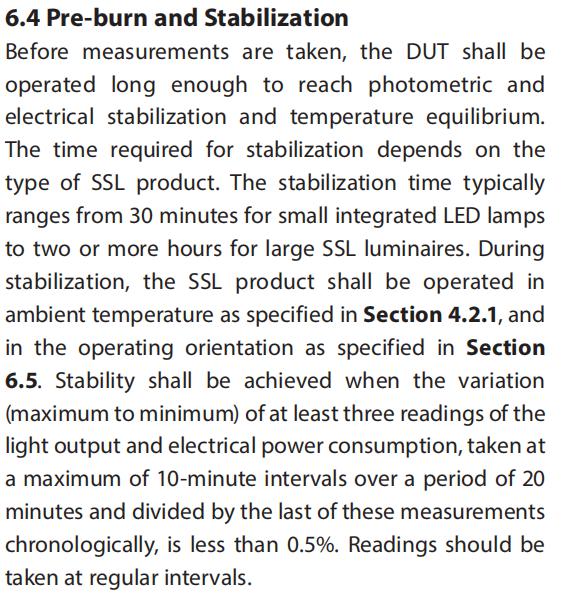
10. Test Report(11.1 on Page 12 of the standard)
10.1 Test date and testing organization
10.2 Manufacture’s name
10.3 Optical parameters measured (e.g., total luminous flux, radiant flux, photon flux)
10.4 Measured electrical values (Clarify AC, including frequency, or DC)
10.5 Calculated quantities (e.g., luminous efficacy, angular color uniformity)
10.6 Ambient temperature
10.7 Measurement conditions. For sphere measurement: Sphere diameter, coating reflectance, 4π or 2π geometry. For goniophotometer measurement: Photometric distance
10.8 SI (source of traceability)
10.9 Self-absorption correction factor
10.10 Luminous intensity
10.11 Chromaticity coordinates, CCT, CRI
10.12 ANSI/IES TM-30-18 (Rg Rf,Local Chroma Shift, Local Hue Shift)
10.13 Spectral power distribution
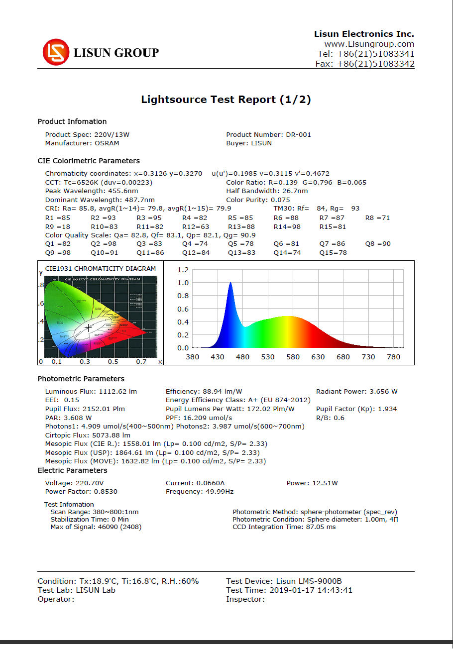
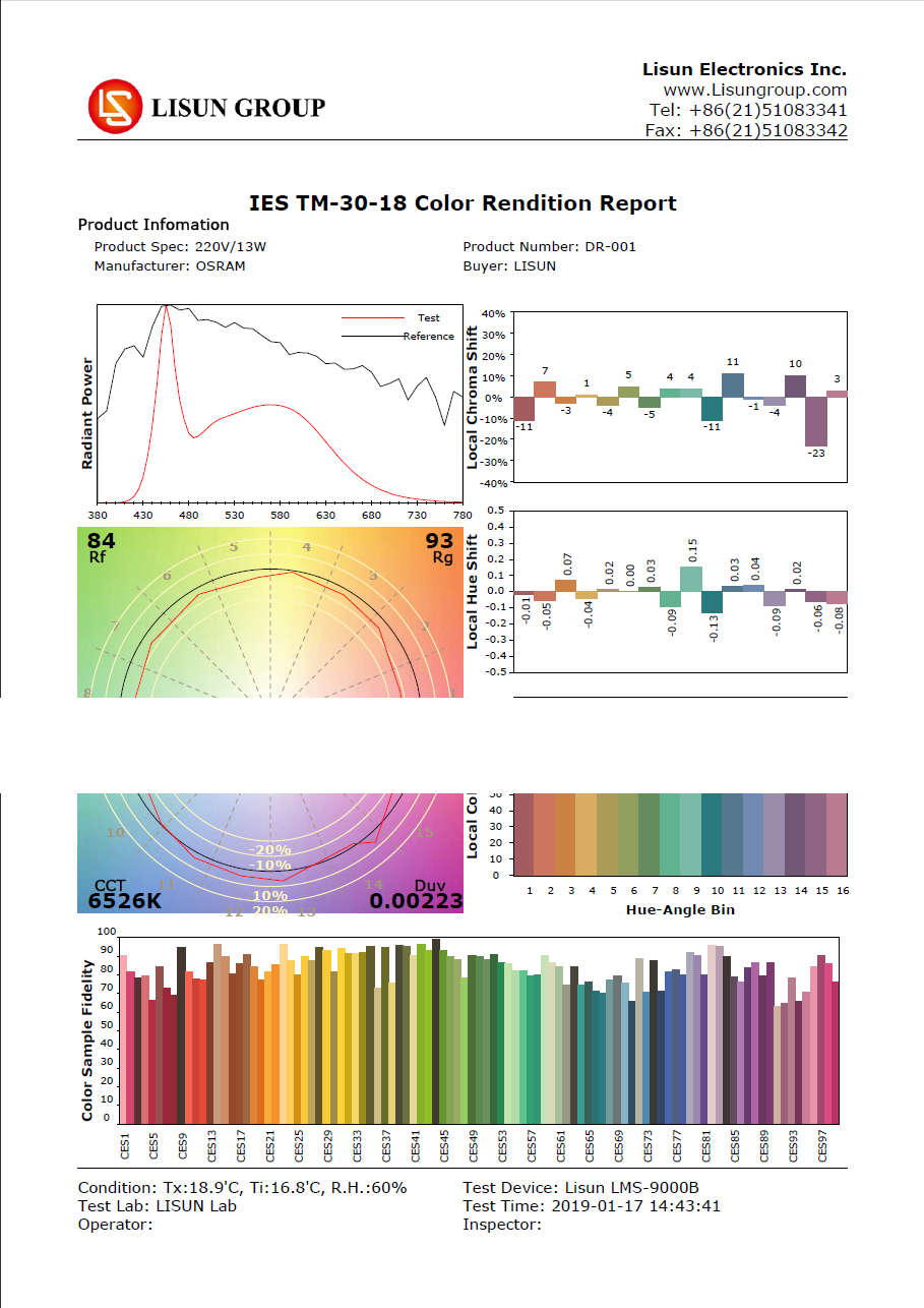
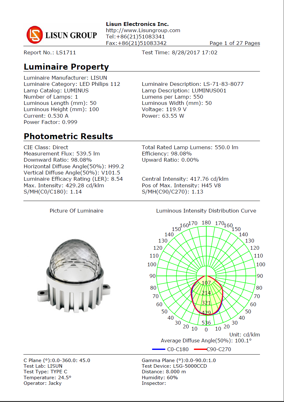
Below is the test report of LPCE-2 High Precision Spectroradiometer Integrating Sphere System and LSG-5000CCD Moving Detector Goniospectroradiometer test system:
Lisun Instruments Limited was found by LISUN GROUP in 2003. LISUN quality system has been strictly certified by ISO9001:2015. As a CIE Membership, LISUN products are designed based on CIE, IEC and other international or national standards. All products passed CE certificate and authenticated by the third party lab.
Our main products are Goniophotometer, Spectroradiometer, Integrating Sphere, LED Test Instruments, CFL Test Instruments, Photometer and Colorimeter, EMC & EMI Testing, Surge Generator, Electrical Safety Testing, Environmental Test Chamber, IP Waterproof Test Equipment, Dustproof Test Chamber, High and Low temperature Humidity Chamber, Plug and Switch Testing, AC and DC Power Supply.
Please feel free to contact us if you need any support.
Tech Dep: Service@Lisungroup.com, Cell/WhatsApp: +8615317907381
Sales Dep: Sales@Lisungroup.com, Cell/WhatsApp: +8618917996096
ANSI (American National Standards Institute) and IES(Illuminating Engineering Society of North America) officially released the latest version of the IES LM-79-19 standard in May 2019, it will replace the LM-79-08 version. LISUN interpreted the new standard as follows:
1. Test Environment (4.2.1 / 4.3 / 4.7 on Page 2 / Page 3 / Page 4 of the standard)
1.1 Ambient Temperature:25℃±1.2℃
1.2 Humidity: 10%-65%
1.3 Airflow: 0.2m/s
2. Test Circuit Requirements (5.2.1 on Page 4 of the standard): Power supply request4-terminal connection, 2- terminal power supply, 2- terminal feedback
3. AC Power Supply (5.1.2 on page 4 of the standard)
3.1 Load regulation rate: ±0.2%
3.2 Accuracy requirements: 0.1% (reading) + 0.1% (range)
3.3 Example: If the power supply of lamp is 220V and the range is 300V, the actual output voltage should be 220V ± 0.26V
LISUN LSP-500VAR Pure Sine Wave AC Power Source fully meet the requirement, click here to learn more about it.
4. DC Power Supply (5.1.3 on Page 4 of the standard)
4.1 Load regulation rate: ±0.2%
4.2 Accuracy requirements: Current and voltage are both 0.1%
LISUN DC3010 Digital CC and CV DC Power Supply fully meet the requirement, click here to learn more about it.
5. AC Power Meters (5.3.2 on Page 5 of the Standard, 5.3.4 on Page 5 of the Standard)
5.1 Sampling frequency : 1kHz-100kHz
5.2 The meter shall have an expanded uncertainty (k=2) of 0.6% or less for measurement frequencies ranging from 0.5Hz to 1kHz, and an expanded unvertainty (k=2) of 2.0% or less for measurement frequencies ranging from 1kHz to 100kHz
5.3 Total Harmonic Distortion Measurement 2~50 times
LISUN LS2050 Digital Power Meter fully meet the requirement. Click here to learn more about it.
6. Photometric probe (7.3.2 on Page 9 of the Standard)
6.1 Cosine angular responsivity f2(ε,φ) less than 2%
6.2 f1’ less than 3%
7. Spectroradiometer (7.3.2 on Page 9 of standard)
7.1 380-780nm
7.2 Bandwidth not greater than 5nm
7.3 Wevelength unvertainty within 0.5nm
7.4 Sensitivity: Refer to LM-78-17 (7.2 on Page 7 of standard)
LISUN LPCE-2 High Precision Spectroradiometer Integrating Sphere System fully meet the requierment, click here to learn more about it.
LPCE-2(LMS 9000) Spectrophotometer & Integrating Sphere Test System
8. Goniometer variable angle tester (7.3.3 on Page 9 of standard)
8.1 For lamps with beam angle < 20°: 100%-50% maximum luminous intensity choose no more than 1 degree angular resolution; 50%-10% maximum luminous intensity choose no more than 2 degrees angular resolution; 10%-0% maximum luminous intensity choose no more than 5 degrees angular resolution;
8.2 For lamps with beam angle ≥20°: 100%-50% maximum luminous intensity choose no more than 2 degrees angular resolution; 50%-0% maximum luminous intensity choose no more than 5 degrees angular resolution。
LISUN LSG-5000CCD Moving Detector Goniospectroradiometer fully meet the requierment, click here to learn more about it.
LSG-5000CCD Moving Detector Goniospectroradiometer
9. Stabilization Requirement (6.4 on Page 7 of standard)
9.1 Monitor for at least 30 minutes
9.2 Take at least three readings of the light output and electrical power consumption taken over period of 20 minutes
9.3 Stability shall be achieved when the variation (maximum to minimum) divided by the last measurements is less than 0.5%
10. Test Report(11.1 on Page 12 of the standard)
10.1 Test date and testing organization
10.2 Manufacture’s name
10.3 Optical parameters measured (e.g., total luminous flux, radiant flux, photon flux)
10.4 Measured electrical values (Clarify AC, including frequency, or DC)
10.5 Calculated quantities (e.g., luminous efficacy, angular color uniformity)
10.6 Ambient temperature
10.7 Measurement conditions. For sphere measurement: Sphere diameter, coating reflectance, 4π or 2π geometry. For goniophotometer measurement: Photometric distance
10.8 SI (source of traceability)
10.9 Self-absorption correction factor
10.10 Luminous intensity
10.11 Chromaticity coordinates, CCT, CRI
10.12 ANSI/IES TM-30-18 (Rg Rf,Local Chroma Shift, Local Hue Shift)
10.13 Spectral power distribution
Below is the test report of LPCE-2 High Precision Spectroradiometer Integrating Sphere System and LSG-5000CCD Moving Detector Goniospectroradiometer test system:
Lisun Instruments Limited was found by LISUN GROUP in 2003. LISUN quality system has been strictly certified by ISO9001:2015. As a CIE Membership, LISUN products are designed based on CIE, IEC and other international or national standards. All products passed CE certificate and authenticated by the third party lab.
Our main products are Goniophotometer, Spectroradiometer, Integrating Sphere, LED Test Instruments, CFL Test Instruments, Photometer and Colorimeter, EMC & EMI Testing, Surge Generator, Electrical Safety Testing, Environmental Test Chamber, IP Waterproof Test Equipment, Dustproof Test Chamber, High and Low temperature Humidity Chamber, Plug and Switch Testing, AC and DC Power Supply.
Please feel free to contact us if you need any support.
Tech Dep: Service@Lisungroup.com, Cell/WhatsApp: +8615317907381
Sales Dep: Sales@Lisungroup.com, Cell/WhatsApp: +8618917996096
Monday, February 24, 2020
How do you choose integrating sphere if you test small size but high power HID lamp?
HID lamp is high intensity discharge lamp. High pressure sodium lamp, high pressure mercury lamp, xenon lamp, metal halide lamp are all belong to HID lamp.
We generally use Integrating Sphere Spectroradiometer Test System to test the photometric, colorimetric and electrometric parameters. Generally we suggest the diameter size of Integrating Sphere according to the size of lamp under test. If you test single LED or LED chips, we recommend small integrating sphere such as IS-0.3M or IS-0.5M. 1.2m luminaries should at least use D=1.5M integrating sphere to measure.
If you test high power small size HID lamp, how do we choose Integrating Sphere? If the power of HID lamp is over 200W, we generally recommend use D=2.0m integrating sphere, we will not suggest small integrating sphere because of these reasons:
Lisun Instruments Limited was found by LISUN GROUP in 2003. LISUN quality system has been strictly certified by ISO9001:2015. As a CIE Membership, LISUN products are designed based on CIE, IEC and other international or national standards. All products passed CE certificate and authenticated by the third party lab.
Our main products are Goniophotometer, Spectroradiometer, Integrating Sphere, LED Test Instruments, CFL Test Instruments, Photometer and Colorimeter, EMC & EMI Testing, Surge Generator, Electrical Safety Testing, Environmental Test Chamber, Waterproof Test , Dustproof Test Chamber, High and Low temperature Humidity Chamber, Plug and Switch Testing, AC and DC Power Supply.
Please feel free to contact us if you need any support.
Tech Dep: Service@Lisungroup.com, Cell/WhatsApp: +8615317907381
Sales Dep: Sales@Lisungroup.com, Cell/WhatsApp: +8618917996096
We generally use Integrating Sphere Spectroradiometer Test System to test the photometric, colorimetric and electrometric parameters. Generally we suggest the diameter size of Integrating Sphere according to the size of lamp under test. If you test single LED or LED chips, we recommend small integrating sphere such as IS-0.3M or IS-0.5M. 1.2m luminaries should at least use D=1.5M integrating sphere to measure.
If you test high power small size HID lamp, how do we choose Integrating Sphere? If the power of HID lamp is over 200W, we generally recommend use D=2.0m integrating sphere, we will not suggest small integrating sphere because of these reasons:
- If integrating sphere is too small, cooling is not good, the temperature of integrating sphere will affect the test result.
- The signal will be too strong, the integration time will be very shot and the test error for lumen will increase.
Lisun Instruments Limited was found by LISUN GROUP in 2003. LISUN quality system has been strictly certified by ISO9001:2015. As a CIE Membership, LISUN products are designed based on CIE, IEC and other international or national standards. All products passed CE certificate and authenticated by the third party lab.
Our main products are Goniophotometer, Spectroradiometer, Integrating Sphere, LED Test Instruments, CFL Test Instruments, Photometer and Colorimeter, EMC & EMI Testing, Surge Generator, Electrical Safety Testing, Environmental Test Chamber, Waterproof Test , Dustproof Test Chamber, High and Low temperature Humidity Chamber, Plug and Switch Testing, AC and DC Power Supply.
Please feel free to contact us if you need any support.
Tech Dep: Service@Lisungroup.com, Cell/WhatsApp: +8615317907381
Sales Dep: Sales@Lisungroup.com, Cell/WhatsApp: +8618917996096
IEC 61000-4-5: Surge Test and Measurement Techniques
Surge generator anti-interference measurement is based on the international standard IEC 61000-4-5.
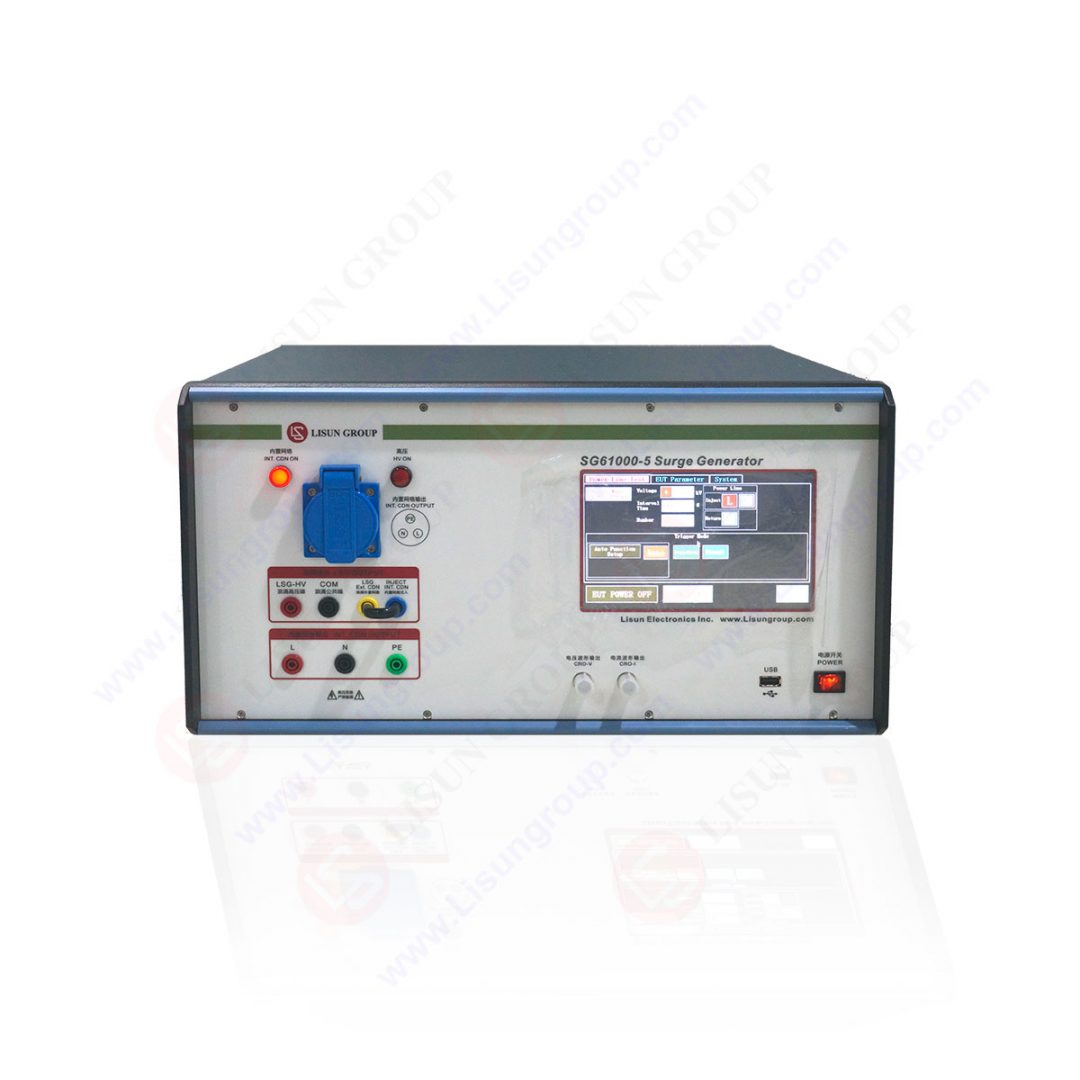 SG61000-5_Surge Generator
1 Test objective
The entire lightning stroke in the nature (namely the indirect thunder such as the lighting stroke between the clouds, or the lighting stroke happened to the adjacent objects) can induce the surge voltage and current in outdoor aerial. Besides, huge surge voltage and current will also be induced in the supply circuit of the instant switch in the power station or switching station. The common characteristics of the two kinds of surge include high energy (compared with the energy, the static electricity is P joule level, pulse group is the millijoule level, lightning surge is hundreds of the joule level, which is one million times of the former two interfering energy), slow waveform (microsecond level, but the static electricity and pulse group are nanosecond level, even the sub nanosecond level), and low recurrence frequency.
IEC 61000-4-5 is a standard that provides an objective evaluation on the resistance to surge interference ability for the electrical and electronic equipment through the experiment of simulating lighting surge.
2 Surge generators
This standard has mentioned two kinds of surge generators, which respectively simulate the situation of the power line and the communication line. The waveforms of the two kinds of surge are different because of the different line impedance.
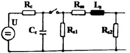
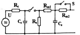
(1)Comprehensive wave generator used for the power lines test
“Comprehensive wave” refers to the waveform parameters formed by the voltage wave and the current wave regulated by the standard in a generator (when the output terminal of the generator is open circuit, it will form the voltage surge wave; when the output terminal of the generator is short circuit, and it will form the current surge wave). The requirement of the generator line and the waveform is shown as the following figures:
IEC 61000-4-5: Surge Test and Measurement Techniques
U: High-voltage power supply
Rs: Pulse duration forming resistor
Rc: Charging resistor
Rm: Impedance matching resistor
Cc: Reservoir capacitance
L: Rising time forming resistor
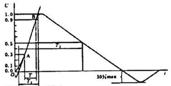
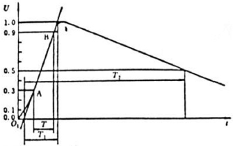
IEC 61000-4-5: Surge Test and Measurement Techniques
Front wave time: T1=1.67XT=1.2μs±30%
Half peak value time: T2=50μs±20%
1.2/50μs Open-circuit voltage waveform (based on IEC 60-1 waveform regulation)
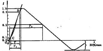
IEC 61000-4-5: Surge Test and Measurement Techniques
Front wave time: T1=1.25XT=8μs±30%
Half peak value time: T2=20μs±20%
8/20μs Open-circuit voltage waveform (based on IEC 60-1 waveform regulation)
The basic requirement of the comprehensive generator:
Open-circuit output voltage (±10%): 0.5kVP to 4kVP
Short-circuit output current (±10%): 0.25kAP to 2kAP
Generator resistance: 2Ω (it is the key to connect the open-circuit voltage wave and the short-circuit current wave)
Additional resistance: 10Ω or 40Ω, form 12Ω or 42Ω internal resistance
Surge output polarity: positive / negative
Surge phase shifting range:0°~360° (surge output synchronizes with the power supply)
Maximum repetition frequency: at least once per minute
(2)10/700μs surge wave generator used for telecommunication line
The generator line and the waveform are shown as the following figure:
U: High-voltage power supply
Rs: Pulse duration forming resistor
Rc: Charging resistor
Cc: Reservoir capacitance (20μF)
Rm: Impedance matching resistor (Rm1=15Ω, Rm2=25Ω)
Cs: Rising time forming resistor (0.2μF)
SG61000-5_Surge Generator
1 Test objective
The entire lightning stroke in the nature (namely the indirect thunder such as the lighting stroke between the clouds, or the lighting stroke happened to the adjacent objects) can induce the surge voltage and current in outdoor aerial. Besides, huge surge voltage and current will also be induced in the supply circuit of the instant switch in the power station or switching station. The common characteristics of the two kinds of surge include high energy (compared with the energy, the static electricity is P joule level, pulse group is the millijoule level, lightning surge is hundreds of the joule level, which is one million times of the former two interfering energy), slow waveform (microsecond level, but the static electricity and pulse group are nanosecond level, even the sub nanosecond level), and low recurrence frequency.
IEC 61000-4-5 is a standard that provides an objective evaluation on the resistance to surge interference ability for the electrical and electronic equipment through the experiment of simulating lighting surge.
2 Surge generators
This standard has mentioned two kinds of surge generators, which respectively simulate the situation of the power line and the communication line. The waveforms of the two kinds of surge are different because of the different line impedance.
(1)Comprehensive wave generator used for the power lines test
“Comprehensive wave” refers to the waveform parameters formed by the voltage wave and the current wave regulated by the standard in a generator (when the output terminal of the generator is open circuit, it will form the voltage surge wave; when the output terminal of the generator is short circuit, and it will form the current surge wave). The requirement of the generator line and the waveform is shown as the following figures:
IEC 61000-4-5: Surge Test and Measurement Techniques
U: High-voltage power supply
Rs: Pulse duration forming resistor
Rc: Charging resistor
Rm: Impedance matching resistor
Cc: Reservoir capacitance
L: Rising time forming resistor
IEC 61000-4-5: Surge Test and Measurement Techniques
Front wave time: T1=1.67XT=1.2μs±30%
Half peak value time: T2=50μs±20%
1.2/50μs Open-circuit voltage waveform (based on IEC 60-1 waveform regulation)
IEC 61000-4-5: Surge Test and Measurement Techniques
Front wave time: T1=1.25XT=8μs±30%
Half peak value time: T2=20μs±20%
8/20μs Open-circuit voltage waveform (based on IEC 60-1 waveform regulation)
The basic requirement of the comprehensive generator:
Open-circuit output voltage (±10%): 0.5kVP to 4kVP
Short-circuit output current (±10%): 0.25kAP to 2kAP
Generator resistance: 2Ω (it is the key to connect the open-circuit voltage wave and the short-circuit current wave)
Additional resistance: 10Ω or 40Ω, form 12Ω or 42Ω internal resistance
Surge output polarity: positive / negative
Surge phase shifting range:0°~360° (surge output synchronizes with the power supply)
Maximum repetition frequency: at least once per minute
(2)10/700μs surge wave generator used for telecommunication line
The generator line and the waveform are shown as the following figure:
IEC 61000-4-5: Surge Test and Measurement Techniques
U: High-voltage power supply
Rs: Pulse duration forming resistor
Rc: Charging resistor
Cc: Reservoir capacitance (20μF)
Rm: Impedance matching resistor (Rm1=15Ω, Rm2=25Ω)
Cs: Rising time forming resistor (0.2μF)
IEC 61000-4-5: Surge Test and Measurement Techniques
S: Switch, this switch should be closed when using the external matching resistance
Front wave time: T1=1.67XT=10μs±30%
Half peak value time: T2=700μs±20%
10/700μs Open-circuit voltage waveform (based on CCITT waveform regulation)Basic requirement of the generator:Open-circuit voltage wave:10/700μsOpen-circuit output voltage(±10%): 0.5kVP to 4kVP
Generator resistance: 40Ω
Surge output polarity: Positive / negative
Half peak value time: T2=700μs±20%
10/700μs Open-circuit voltage waveform (based on CCITT waveform regulation)Basic requirement of the generator:Open-circuit voltage wave:10/700μsOpen-circuit output voltage(±10%): 0.5kVP to 4kVP
Generator resistance: 40Ω
Surge output polarity: Positive / negative
3 Test methods
Since the voltage and the current of the surge test are relatively slow, the configuration of the lab is rather simple. The power circuit test is finished through coupling decoupling network. The following figure is the single-phase test circuit diagram which has the requirement of the differential mode and common mode test.
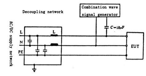
Since the voltage and the current of the surge test are relatively slow, the configuration of the lab is rather simple. The power circuit test is finished through coupling decoupling network. The following figure is the single-phase test circuit diagram which has the requirement of the differential mode and common mode test.
IEC 61000-4-5: Surge Test and Measurement Techniques
4 Attention in the test
(1)Protective measures must be taken in accordance with the requirement of the manufacturer before the test.
(2) The test rate is once per minute. It should not be too quick so as to form a recovery process for protecting the machine’s performance. As a matter of fact, it is impossible for the natural lighting phenomenon and the large switch of the transformer substation to have very high repetition rate. In general, there are five -times test for each positive and negative polarity.
(3) The voltage should be gradually tested from low level to high level to avoid the false scent of the sample I-V nonlinear characteristics. In addition, the test voltage should be confirmed not to exceed the requirement of the product standard in order to avoid the unnecessary damage.
5 Severe degree of the test
The severe degree of the test can be divided into 1, 2, 3, and 4 and X level. Level 13 parameter of the power circuit differential mode is not given, the other levels are respectively 0.5kV、1kV、2kV and undetermined. Each level parameter of the power circuit common mode test is 0.5kV、1kV、2kV、4kV and undetermined.
The severe degree of the test depends on the environment (the environment that may suffer the surge) and the installation condition; it is mainly divided into the following types:
Level 1: Better protective environment, such as the control room of the factories or the power station.
Level 2: Certain protective environment such as factories with no strong interference.
Level 3: Common electromagnetic harassment environment without specified installation requirement for the equipment such as the cable network of common installation, industrial work place and power substation.
Level 4: Severe harassment environment such as civil aerial, high-pressure power substation without protection.
Level X: Special level should be confirmed after the consultation of the user and the manufacturer.Selection of the product level depends on the product standard.
6 Comment on the standards
At present, there are many standards mentioning the situation of using 1.2/50μs lighting to do the test, but the different standard has different test objective. For example, high-pressure test also mentioned the lighting test for the impulse withstand voltage test with the high-pressure and high-resistance generator. At this moment, although the voltage of the generator is high, the energy is not huge. This kind of test is conducted in the off-line state of the equipment. On the contrary, IEC 61000-4-5 standard requires conducting the surge anti-interference measurement. Due to the low circuit impedance, the output impedance of the generator is also required to be low. In this way, the generator suitable for surge anti-interference measurement not only needs to have high output voltage, but also needs to have low output impedance and large energy output characteristics. Since the equipment conducts the measurement in the on-line state, coupling and decoupling network should be used. It can be seen that the above mentioned two kinds of experiments are totally different, which should not be confused.
Lisun Instruments Limited was found by LISUN GROUP in 2003.LISUN quality system has been strictly certified by ISO9001:2015. As a CIE Membership, LISUN products are designed based on CIE, IEC and other international or national standards. All products passed CE certificate and authenticated by the third party lab.
Our main products are Goniophotometer, Spectroradiometer Integrating Sphere System, LED Test Instruments, EMC & EMI Testing, Surge Generator, Electrical Safety Testing, Environmental Test Chamber, Waterproof Test ,Dustproof Test , High and Low temperature Humidity Chamber, Plug and Switch Testing,etc.
Please feel free to contact us if you need any support.
Tech Dep: Service@Lisungroup.com, Cell/WhatsApp:+8615317907381
Sales Dep: Sales@Lisungroup.com, Cell/WhatsApp:+8618917996096
Friday, February 21, 2020
How to Use TM-21 to Estimate LED Luminaries Life?
LED has the features of long time. According to different power drivers and use conditions, the life of LED can be up to 50,000 hours pr more. LED will not extinguish directly like other light source but decay gradually. Therefore, luminous decay will lead to output low light after long time use, which will make products not meet requirements. And how to use TM-21 to estimate LED luminaries life?
In order that LED industry persons have a clear concept of TM-21 and learn how to use TM-21 to estimate LED products. We will make 4 programs to explain the application and prediction method of LM-80-08 and TM-21-11:
Step 1: LED components manufacturers do at least 6,000 hours test at 3 temperatures (55C°/85 C°/Optional Temperature) for LED Source (Package/Array/Module) according to LM-80-08.
Required samples number: (Related to the prediction time)
Test Time Requirement (Related to Prediction Accuracy)
At least 6,000 Hours, recommend 10,000 Hours, you should obtain the LED light attenuation information every 1,000 hours, interval time is shorter(such as 500 hours), which can improve the accuracy of the prediction time.
Step 2: Predict 3 test temperatures (55C°/85 C°/Optional Temperature) long life information according to TM-21-11.
Obtain the average value of experiment data at each temperature, the time rules to take test information as follow:
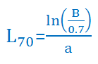
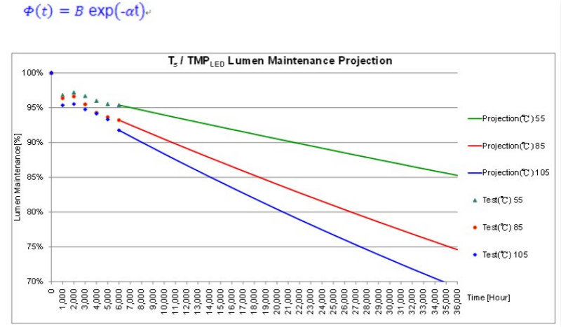
According to formula, calculate the 70% lumen maintenance life time value at every temperature experiment under ENERGY STAR standard.y=mx+b, B=exp(b), a=-mUse Exponential Least Squares Curve-Fit to get Slope m and Intercept b, when calculate m and b, the interval is denser if test time is longer, its accuracy will increase and then calculate the value of B and α.
L70: Time to 70% lumen maintenance
Use sample number in Step 1 to predict multiple times standard to judge:
(6K) : LM-80 Test Time; (6K)=6,000 Hours; (10K)=10,000 HoursRepresentation: L70(6K) = XX,XXX hours
XX,XXX Hours : Sample≧20ea, Test Time=6,000, Predict 6 times to 36,000 hours
Use Exponential Formation to calculate the lumen maintenance of every time, and then draw the prediction life curve at every test temperature according to the calculated data.
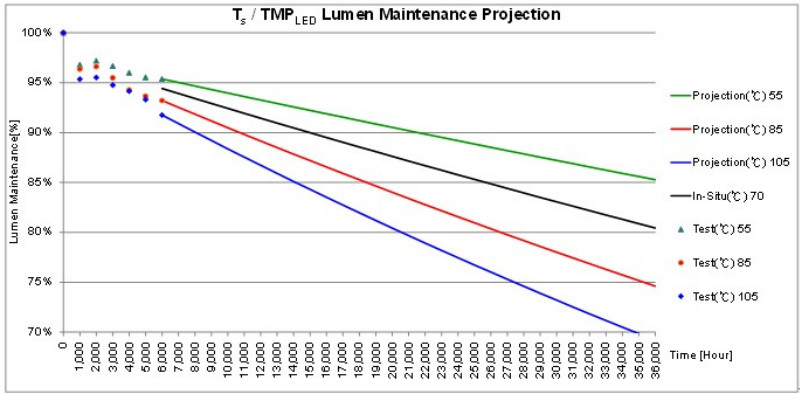
Step 3: Obtain In Situ Temperature of this LED devise in LED luminaries.
Please refer to ISTMT(In Situ Temperature Measurement Test) formula to obtain the temperature of LED device in LED lumunaries, this test temperature position must be same with Ts set position of LM-80-08, the temperature data taken out is called TMPLED(LED Temperature Measurement Point).
Step 4: Use the calculation results of TMPLED and TM-21 to do Interpolation calculation, to obtain the estimated life value of TMPLED.
Select two close-in temperature points cladding in TMPLED from 3 test temperature points as calculation datum point.
Calculate Arrhenius Model temperature acceleration parameter A and get Decay Rate: α and Fixed value parameter B0.
Use upper formula to calculate the L70 value of TMPLED, same formula represents the result of TMPLED.
L70(6K) > XX,XXX hours

Set into relevant time value and draw the life time prediction curve of TMPLED and 3 Ts.
Lisun LEDLM-80PL LED Lumen Maintenance and Aging Life Test System is designed according to IES-LM-80 standards. This system combines Arrhenius Model, which can make users predict L30 and L70 etc lumen maintenance by software after hundreds to thousands of hours test.
Lisun Instruments Limited was found by LISUN GROUP in 2003. LISUN quality system has been strictly certified by ISO9001:2015. As a CIE Membership, LISUN products are designed based on CIE, IEC and other international or national standards. All products passed CE certificate and authenticated by the third party lab.
Our main products are Goniophotometer, Spectroradiometer, Integrating Sphere, LED Test Instruments, CFL Test Instruments, Photometer and Colorimeter, EMC & EMI Testing, Surge Generator, Electrical Safety Testing, Environmental Test Chamber, Waterproof Test , Dustproof Test Chamber, High and Low temperature Humidity Chamber, Plug and Switch Testing, AC and DC Power Supply.
Please feel free to contact us if you need any support.
Tech Dep: Service@Lisungroup.com, Cell/WhatsApp:+8615317907381
Sales Dep: Sales@Lisungroup.com, Cell/WhatsApp:+8618917996096
In order that LED industry persons have a clear concept of TM-21 and learn how to use TM-21 to estimate LED products. We will make 4 programs to explain the application and prediction method of LM-80-08 and TM-21-11:
Step 1: LED components manufacturers do at least 6,000 hours test at 3 temperatures (55C°/85 C°/Optional Temperature) for LED Source (Package/Array/Module) according to LM-80-08.
Required samples number: (Related to the prediction time)
| Samples for eachTs | Luminaires V1.1 | LED Lamps V1.4 |
| LED Package | ≥20 | ≥25 |
| LED Mpdul / Array | ≥10 | ≥10 |
Test Time Requirement (Related to Prediction Accuracy)
At least 6,000 Hours, recommend 10,000 Hours, you should obtain the LED light attenuation information every 1,000 hours, interval time is shorter(such as 500 hours), which can improve the accuracy of the prediction time.
Step 2: Predict 3 test temperatures (55C°/85 C°/Optional Temperature) long life information according to TM-21-11.
Obtain the average value of experiment data at each temperature, the time rules to take test information as follow:
| D Test Time (Hour) | Take out the data principle |
| 6000~10000 | 1. Take out the last 5,000 hours to calculate2. 0~1,000 hours data do not use(LED Unstable Period) |
| >10,000 | 1. Take out last 50% that is D/2~D to calculate |
According to formula, calculate the 70% lumen maintenance life time value at every temperature experiment under ENERGY STAR standard.y=mx+b, B=exp(b), a=-mUse Exponential Least Squares Curve-Fit to get Slope m and Intercept b, when calculate m and b, the interval is denser if test time is longer, its accuracy will increase and then calculate the value of B and α.
L70: Time to 70% lumen maintenance
Use sample number in Step 1 to predict multiple times standard to judge:
| Sample Number (Per Temperature) | TM-21 Prediction Multiple Time |
| ≥20ea | 6 times of the test time |
| ≥10ea,<20ea | 5.5 times of the test time |
| <10ea | Not applicable for TM-21 |
(6K) : LM-80 Test Time; (6K)=6,000 Hours; (10K)=10,000 HoursRepresentation: L70(6K) = XX,XXX hours
XX,XXX Hours : Sample≧20ea, Test Time=6,000, Predict 6 times to 36,000 hours
Use Exponential Formation to calculate the lumen maintenance of every time, and then draw the prediction life curve at every test temperature according to the calculated data.
Step 3: Obtain In Situ Temperature of this LED devise in LED luminaries.
Please refer to ISTMT(In Situ Temperature Measurement Test) formula to obtain the temperature of LED device in LED lumunaries, this test temperature position must be same with Ts set position of LM-80-08, the temperature data taken out is called TMPLED(LED Temperature Measurement Point).
Step 4: Use the calculation results of TMPLED and TM-21 to do Interpolation calculation, to obtain the estimated life value of TMPLED.
Select two close-in temperature points cladding in TMPLED from 3 test temperature points as calculation datum point.
Calculate Arrhenius Model temperature acceleration parameter A and get Decay Rate: α and Fixed value parameter B0.
Use upper formula to calculate the L70 value of TMPLED, same formula represents the result of TMPLED.
L70(6K) > XX,XXX hours
Set into relevant time value and draw the life time prediction curve of TMPLED and 3 Ts.
Lisun LEDLM-80PL LED Lumen Maintenance and Aging Life Test System is designed according to IES-LM-80 standards. This system combines Arrhenius Model, which can make users predict L30 and L70 etc lumen maintenance by software after hundreds to thousands of hours test.
Lisun Instruments Limited was found by LISUN GROUP in 2003. LISUN quality system has been strictly certified by ISO9001:2015. As a CIE Membership, LISUN products are designed based on CIE, IEC and other international or national standards. All products passed CE certificate and authenticated by the third party lab.
Our main products are Goniophotometer, Spectroradiometer, Integrating Sphere, LED Test Instruments, CFL Test Instruments, Photometer and Colorimeter, EMC & EMI Testing, Surge Generator, Electrical Safety Testing, Environmental Test Chamber, Waterproof Test , Dustproof Test Chamber, High and Low temperature Humidity Chamber, Plug and Switch Testing, AC and DC Power Supply.
Please feel free to contact us if you need any support.
Tech Dep: Service@Lisungroup.com, Cell/WhatsApp:+8615317907381
Sales Dep: Sales@Lisungroup.com, Cell/WhatsApp:+8618917996096
Surge generator: IEC 61000-4-5-2014 Surge Immunity Test
The International Electrotechnical Commission (IEC) has published IEC 61000-4-5:2014, “Electromagnetic Compatibility (EMC) – Part 4-5: Testing and Measurement Techniques – Surge Immunity Test.”
“IEC 61000-4-5:2014 relates to the immunity requirements, test methods and range of recommended test levels for equipment with regard to unidirectional surges caused by over-voltages from switching and lightning transients. Several test levels are defined which relate to different environment and installation conditions. These requirements are developed for and are applicable to electrical and electronic equipment. The object of this standard is to establish a common reference for evaluating the immunity of electrical and electronic equipment when subjected to surges.”
“The test method documented describes a consistent method to assess the immunity of an equipment or system against a defined phenomenon. This standard defines a range of:
“This third edition cancels and replaces the second edition published in 2005, and constitutes a technical revision which includes the following significant technical changes with respect to the previous edition:
LISUN SG61000-5 Surge Generator is exactly according to the latest version of this IEC standard. SG61000-5_Surge Generator
Lisun Instruments Limited was found by LISUN GROUP in 2003.LISUN quality system has been strictly certified by ISO9001:2015. As a CIE Membership, LISUN products are designed based on CIE, IEC and other international or national standards. All products passed CE certificate and authenticated by the third party lab.
Our main products are Goniophotometer, Spectroradiometer Integrating Sphere System, LED Test Instruments, EMC & EMI Testing, Surge Generator, Electrical Safety Testing, Environmental Test Chamber, Waterproof Test ,Dustproof Test , High and Low temperature Humidity Chamber, Plug and Switch Testing,etc.
Please feel free to contact us if you need any support.
Tech Dep: Service@Lisungroup.com, Cell/WhatsApp:+8615317907381
Sales Dep: Sales@Lisungroup.com, Cell/WhatsApp:+8618917996096
“IEC 61000-4-5:2014 relates to the immunity requirements, test methods and range of recommended test levels for equipment with regard to unidirectional surges caused by over-voltages from switching and lightning transients. Several test levels are defined which relate to different environment and installation conditions. These requirements are developed for and are applicable to electrical and electronic equipment. The object of this standard is to establish a common reference for evaluating the immunity of electrical and electronic equipment when subjected to surges.”
“The test method documented describes a consistent method to assess the immunity of an equipment or system against a defined phenomenon. This standard defines a range of:
- test levels;
- test equipment;
- test setups;
- test procedures.”
“This third edition cancels and replaces the second edition published in 2005, and constitutes a technical revision which includes the following significant technical changes with respect to the previous edition:
- a new Annex E on mathematical modelling of surge waveforms;
- a new Annex F on measurement uncertainty;
- a new Annex G on method of calibration of impulse measuring systems;
- a new Annex H on coupling/decoupling surges to lines rated above 200 A.”
LISUN SG61000-5 Surge Generator is exactly according to the latest version of this IEC standard.
SG61000-5_Surge GeneratorLisun Instruments Limited was found by LISUN GROUP in 2003.LISUN quality system has been strictly certified by ISO9001:2015. As a CIE Membership, LISUN products are designed based on CIE, IEC and other international or national standards. All products passed CE certificate and authenticated by the third party lab.
Our main products are Goniophotometer, Spectroradiometer Integrating Sphere System, LED Test Instruments, EMC & EMI Testing, Surge Generator, Electrical Safety Testing, Environmental Test Chamber, Waterproof Test ,Dustproof Test , High and Low temperature Humidity Chamber, Plug and Switch Testing,etc.
Please feel free to contact us if you need any support.
Tech Dep: Service@Lisungroup.com, Cell/WhatsApp:+8615317907381
Sales Dep: Sales@Lisungroup.com, Cell/WhatsApp:+8618917996096
Thursday, February 20, 2020
How to Test the LED Junction Temperature?
We know that the life of LED is closely related to its junction temperature. The key to prolonging its life is to reduce its junction temperature. And the key to reduce the junction temperature is to have a good heat sink that able to exhaust the heat generated by LED in time.
So, how to measure the junction temperature of LED?
Junction temperature seems to be a temperature measurement problem, but the junction temperature need to measure is in the internal of LED. Can’t we measure its temperature with a thermometer or a thermocouple into the PN junction. Of course, its shell temperature can be measured with thermocouple, and then its junction temperature can be calculated according to the thermal resistance Rjc (junction to the shell).
But things become more complicated after installing the radiator. Because usually LED is welded to the aluminum substrate, and the aluminum substrate is installed on the radiator. If you can only measure the temperature of the radiator shell, then it is necessary to know the value of a lot of thermal resistance to calculate the junction temperature.
Including Rjc (junction to case), Rcm (shell to the aluminum substrate, in fact, which also should include film printed version of the thermal resistance), Rms (aluminum substrate to the radiator), Rsa (heat sink to air), which only with one inaccurate data will affect the accuracy of the test. Figure 1 shows a schematic diagram of the LED to each thermal resistance of radiator. Where incorporates a lot of thermal resistance, making it more precision limited. That is to say, the accuracy of the junction temperature would be worse when inferred from the surface temperature of the radiator.
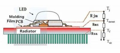
Figure-1-Schematic-diagram-of-LED-to-each-thermal-resistance-of-the-radiator
Fortunately, there is an indirect method of measuring temperature that is to measure the voltage. Then the junction temperature is relative to which voltage? And what is the relationship?
Firstly, we should talk about the characteristics of LED volt-ampere.
We know that the LED is a semiconductor diode, which has a volt-ampere characteristic same as all diodes. The volt ampere characteristic has a temperature characteristic that is when the temperature raises, the volt ampere characteristic left shifts. The Figure. 2. shows temperature characteristics of the LED’s volt ampere.
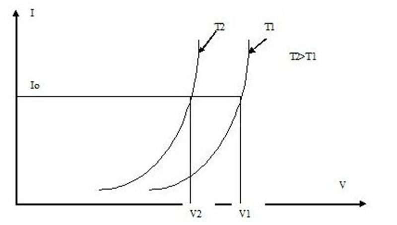
Figure-2-Temperature-characteristics-of-LED-volt-ampere
Assuming that the LED is powered by a Io constant current, when the voltage is T1, the voltage is V1. While the junction temperature rises to T2, the entire volt ampere characteristic is left shifted, the current Io is constant, the voltage changes to V2. The two voltage difference is removed by temperature, then the temperature coefficient can be obtained and shown by mV/oC. For ordinary silicon diodes, the temperature coefficient is about -2mV/oC.
But the LED is not made of silicon material, so its temperature coefficient should also be measured additionally. Fortunately, most of the LED manufacturers give its temperature coefficient in the data table. Take XLamp7090XR-E high power LED for example, its temperature coefficient is -4mV/oC, and 2 times larger than the ordinary silicon diode. The volt ampere characteristic temperature coefficient of Luxeon Rebel from a company of USA is -2 – 4mV/oC. As for LED Puri array (BXRA) of the USA, it gives more detailed data.
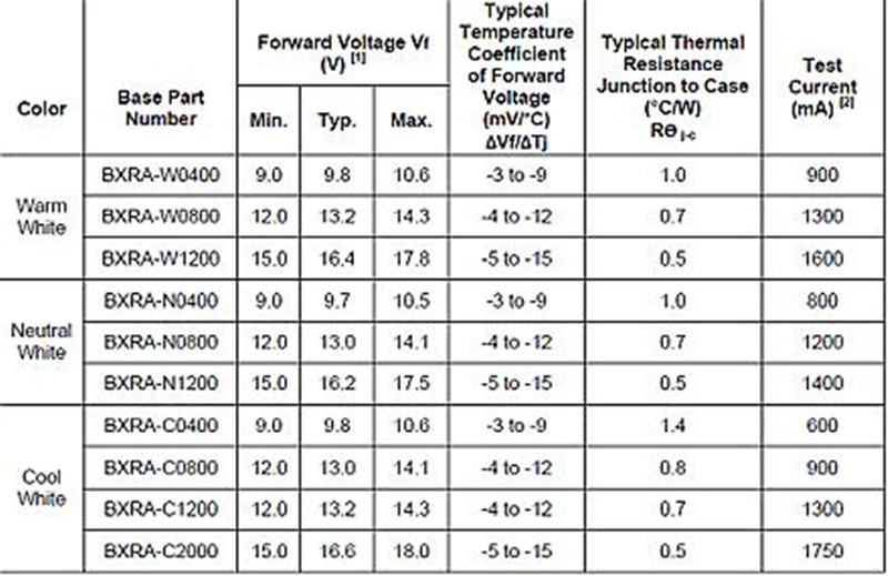 Figure-3-Decay-curves-of-LuxeonK2
However, the range of the data is too large, so that may loss the value of the using. Anyway, as long as the temperature coefficient of the LED is known, the LED junction temperature can be calculated from the forward voltage of the LED.
Lisun developed the T3 LED junction temperature thermal resistance electrical characteristic test, it can automatically record the changes of the parameters with time curve.
Lisun Instruments Limited was found by LISUN GROUP in 2003. LISUN quality system has been strictly certified by ISO9001:2015. As a CIE Membership, LISUN products are designed based on CIE, IEC and other international or national standards. All products passed CE certificate and authenticated by the third party lab.
Our main products are Goniophotometer, Spectroradiometer, Integrating Sphere, LED Test Instruments, CFL Test Instruments, Photometer and Colorimeter, EMC & EMI Testing, Surge Generator, Electrical Safety Testing, Environmental Test Chamber, Waterproof Test , Dustproof Test Chamber, High and Low temperature Humidity Chamber, Plug and Switch Testing, AC and DC Power Supply.
Please feel free to contact us if you need any support.
Tech Dep: Service@Lisungroup.com, Cell/WhatsApp:+8615317907381
Sales Dep: Sales@Lisungroup.com, Cell/WhatsApp:+8618917996096
So, how to measure the junction temperature of LED?
Junction temperature seems to be a temperature measurement problem, but the junction temperature need to measure is in the internal of LED. Can’t we measure its temperature with a thermometer or a thermocouple into the PN junction. Of course, its shell temperature can be measured with thermocouple, and then its junction temperature can be calculated according to the thermal resistance Rjc (junction to the shell).
But things become more complicated after installing the radiator. Because usually LED is welded to the aluminum substrate, and the aluminum substrate is installed on the radiator. If you can only measure the temperature of the radiator shell, then it is necessary to know the value of a lot of thermal resistance to calculate the junction temperature.
Including Rjc (junction to case), Rcm (shell to the aluminum substrate, in fact, which also should include film printed version of the thermal resistance), Rms (aluminum substrate to the radiator), Rsa (heat sink to air), which only with one inaccurate data will affect the accuracy of the test. Figure 1 shows a schematic diagram of the LED to each thermal resistance of radiator. Where incorporates a lot of thermal resistance, making it more precision limited. That is to say, the accuracy of the junction temperature would be worse when inferred from the surface temperature of the radiator.
Figure-1-Schematic-diagram-of-LED-to-each-thermal-resistance-of-the-radiator
Fortunately, there is an indirect method of measuring temperature that is to measure the voltage. Then the junction temperature is relative to which voltage? And what is the relationship?
Firstly, we should talk about the characteristics of LED volt-ampere.
We know that the LED is a semiconductor diode, which has a volt-ampere characteristic same as all diodes. The volt ampere characteristic has a temperature characteristic that is when the temperature raises, the volt ampere characteristic left shifts. The Figure. 2. shows temperature characteristics of the LED’s volt ampere.
Figure-2-Temperature-characteristics-of-LED-volt-ampere
Assuming that the LED is powered by a Io constant current, when the voltage is T1, the voltage is V1. While the junction temperature rises to T2, the entire volt ampere characteristic is left shifted, the current Io is constant, the voltage changes to V2. The two voltage difference is removed by temperature, then the temperature coefficient can be obtained and shown by mV/oC. For ordinary silicon diodes, the temperature coefficient is about -2mV/oC.
But the LED is not made of silicon material, so its temperature coefficient should also be measured additionally. Fortunately, most of the LED manufacturers give its temperature coefficient in the data table. Take XLamp7090XR-E high power LED for example, its temperature coefficient is -4mV/oC, and 2 times larger than the ordinary silicon diode. The volt ampere characteristic temperature coefficient of Luxeon Rebel from a company of USA is -2 – 4mV/oC. As for LED Puri array (BXRA) of the USA, it gives more detailed data.
Figure-3-Decay-curves-of-LuxeonK2
However, the range of the data is too large, so that may loss the value of the using. Anyway, as long as the temperature coefficient of the LED is known, the LED junction temperature can be calculated from the forward voltage of the LED.
Lisun developed the T3 LED junction temperature thermal resistance electrical characteristic test, it can automatically record the changes of the parameters with time curve.
Lisun Instruments Limited was found by LISUN GROUP in 2003. LISUN quality system has been strictly certified by ISO9001:2015. As a CIE Membership, LISUN products are designed based on CIE, IEC and other international or national standards. All products passed CE certificate and authenticated by the third party lab.
Our main products are Goniophotometer, Spectroradiometer, Integrating Sphere, LED Test Instruments, CFL Test Instruments, Photometer and Colorimeter, EMC & EMI Testing, Surge Generator, Electrical Safety Testing, Environmental Test Chamber, Waterproof Test , Dustproof Test Chamber, High and Low temperature Humidity Chamber, Plug and Switch Testing, AC and DC Power Supply.
Please feel free to contact us if you need any support.
Tech Dep: Service@Lisungroup.com, Cell/WhatsApp:+8615317907381
Sales Dep: Sales@Lisungroup.com, Cell/WhatsApp:+8618917996096
How to Solve the Stroboscopic Problem of LED Lighting?
“Bright blind” in life is an exaggerated description of some impact incidents, but if it is used for the LED lighting industry, then it is the quality problems of LED lamp itself. And “strobe” is likely the initiator to lead to “blind”. Many people are not very clear about the concept of strobe, and even don’t care about its harm. Regarding the hazard of strobe, experts have given the conclusion.
A lot of LED lights on the market use the pulse power supply, their cost is relatively cheap, at the same time conducive to adjust the brightness, and also extend the working life of lamp. However, it is not a continuous light, but flicker in a very high speed, we can not see with naked eye. Only our brain and retina can detect the strobe. This kind of flicker may cause headaches, decreased attention and vision loss.
Energy Bureau staff told the media that the government should exert more attention to this problem, improve the laws and regulations, so that make unqualified products disappear from the market. At the same time, he stressed that the LED energy saving light technology will be better and better. Compared with the old light bulb, the consumption of LED lamp is only its 1/10, so this act may also plays an active significance to energy saving.
For there is strobe or not, users can use a simple method to distinguish. Firstly, turn on the light and then open mobile phone camera function, put the camera lens at a distance of 20cm from the lamp, then observe whether there is a dark stripe flicker in the phone camera screen. If there is flicker, then this lamp has strobe, if there is no flicker, then you can use this lamp rest assured.
Dated 14th December, 2012, the EU officially released the (EU) NO 1194/2012 rules implementing rules of the European Parliament and the EU Council Directive 2009/125/EC on the eco-design requirements of directional lights, LED lights and related equipment requirements. Compared with European Parliament and Council Directive 2005/32/EC implementing rules for non-directional household lamps eco-design requirements which posted by the European Commission Regulation (EC) NO 244/2009 Regulations dated 18th March, 2009, the new rules have complete mandatory and eco-design requirements.
For LED manufacturers, they can only use professional testing equipment to detect the stroboscopic problem of LED. The LSRF-1 Lamp Start, Run-up time and Flicker Test from Lisun Electronic (Shanghai) office is integrated equipment which can test Lamp Start, Run-up Time and Flicker. To meet EU ErP requirements, IEC60969 Self-ballasted Lamps for General Lighting Services Performance requirements and Energy Star about Lamp Start, Run-up Time and Flicker Test. LISUN developed ErP test system, the system hardware consists of PH3000 and LSP-500VAC; the software consists of LST-3000 Lamp Start and Run-up Time Test and FLK-3000 Lamp Flick Test.
Lisun Electronic (Shanghai) office is committed to the development and after-sales maintenance of lighting instrument, EMI / EMC test system and Electrical Safety Tester in the domestic and global market. The full range of products of Lisun are in strict accordance with the quality management and control of ISO9001:2008 requirements for R & D and production; Lisun is also the member of global lighting CIE association, all products are according to CIE requirements; in addition, all products of Lisun are certified by CE and get the qualification of the EU.
Monday, February 17, 2020
How to predict the life of LED?
In general, LED can be used for more than 50000 hours, and some manufacturers are promoting their LED to operate for about 100000 hours. The main problem in this area is that LED is not simply no longer operational. Its rated service life can not be calculated by traditional lamps and lanterns. In fact, when testing the life of LED, no one will be waiting for it to stop functioning. However, there are other ways to measure the life of LED. The reason why LED is durable is that it does not produce filament fuses. LED will not stop operation directly, but it will gradually deteriorate over time. It is predicted that high quality LED can maintain more than 60% of the initial lamp brightness after 50000 hours of continuous operation. Assuming that LED has reached its rated service life, it may still be luminous, but the light is very weak.
Without considering the power and driving failures, the life span of LED is characterized by its decay, that is, the longer the time is, the more darker the brightness will be, until finally extinguished. The time of decay of 30% is usually defined as its life. So can the life of LED be predicted?
1. Light failure of LED
Most white LED is obtained by irradiating yellow phosphor with blue LED. There are two main reasons for LED fading. One is the decay of Blu ray LED itself, and the blue light LED has far more light decay than red light, yellow light and green light LED. Another is the decay of phosphor, and the attenuation of phosphor at high temperature is very serious.
The decay of LED is related to its junction temperature. The so-called junction temperature is the temperature of the semiconductor pn junction. The higher the junction temperature is, the earlier the decay occurs, that is, the shorter the life. If the junction temperature is 105 degrees, the lifetime of the brightness to 70% is only more than 10000 hours, 95 degrees will be 20 thousand hours, and the junction temperature is reduced to 75 degrees, the life will be 50 thousand hours, and 65 degrees can be extended to 90 thousand hours. So the key to prolonging life is to reduce junction temperature. But these data are only suitable for Cree’s LED. It’s not suitable for other companies’ LED. When the junction temperature is increased from 115 to 135, the life will be reduced from 50000 hours to 20000 hours.
2. How can we prolong the life of LED?
The key to prolonging its life is to reduce its junction temperature. The key to lowering the junction temperature is to have good radiator. It is able to send out the heat generated by LED in time.
3. How to predict the life of this lamp.
Judging from the junction temperature, life expectancy should be very simple. You can know that the life of LED can reach 20 thousand hours at the temperature of 95 knots. However, this method for indoor LED lamps and lanterns has certain credibility, if applied to outdoor LED lamps, especially high power LED street lamps, there are many uncertainties. The biggest problem is that the heat dissipation efficiency of the LED Street radiators decreases with time. This is due to the accumulation of dust and bird droppings, resulting in reduced heat dissipation efficiency. Also because there is a strong ultraviolet light outside, it will also reduce the life of LED. Ultraviolet radiation plays an important role in the aging of encapsulated epoxy resin. If silica gel is used, it can be improved. Ultraviolet radiation also has some bad effects on the aging of phosphors, but it is not very serious.
The LEDLM-80PL LED luminous flux maintenance rate and aging life testing system, launched by Shanghai power Shantou, are designed and manufactured according to the CIE and IEC standards such as IES-LM-80, IES-LM-82, TM-21, GB2312-80 and so on. It can record the curve of luminous flux with time and the curve of color parameter changing with time. The life time of LED is calculated by testing the data of light decay for a short time.
Lisun Instruments Limited was found by LISUN GROUP in 2003. LISUN quality system has been strictly certified by ISO9001:2015. As a CIE Membership, LISUN products are designed based on CIE, IEC and other international or national standards. All products passed CE certificate and authenticated by the third party lab.
Our main products are Goniophotometer, Spectroradiometer, Integrating Sphere, LED Test Instruments, CFL Test Instruments, Photometer and Colorimeter, EMC & EMI Testing, Surge Generator, Electrical Safety Testing, Environmental Test Chamber, Waterproof Test , Dustproof Test Chamber, High and Low temperature Humidity Chamber, Plug and Switch Testing, AC and DC Power Supply.
Please feel free to contact us if you need any support.
Tech Dep: Service@Lisungroup.com, Cell/WhatsApp:+8615317907381
Sales Dep: Sales@Lisungroup.com, Cell/WhatsApp:+8618917996096
How to Measure the High Frequency Fluorescent Lamp
High frequency fluorescent lamp came out in 1990. Fine tube, small current and high power is the distinct features. Because of the above design structure, high frequency current working, electronic ballast with low power consumption, the work system of this high frequency fluorescent lamp is superior to the traditional lamp on the aspect of lighting effect and photometric.
How to measure the characters of the fluorescent lamp in high frequency condition? How to verify the match relationship of the tube and ballast? These problems always trouble the fluorescent tubes manufacture enterprise and the third lab service company. Lisun Group supplies the following two solutions: IEC Standard Test Method and High Frequency Constant Current Equivalent Test Method.
1. IEC Standard Test Method:
Double end fluorescent lamp adopts the IEC 60081 (GB/T10682) and the single-ended fluorescent lamp adopts the IEC 60901 (GB/T17262), where in the standard of electricity parameters as in Fig 1. As we know the testing correctness of the photo & color parameters are based on the fact that the reference ballast, power and instrument in the detection circuit all comply with standards. If the reference ballast, power and instrument can’t meet the standard that means it can not supply the tube with standard working conditions. Then, not only the tested electricity parameter but also the photo & color parameters will deviate from the actual value obviously.
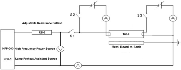
Fig 1 Preheating Method of Cathode High Frequency Fluorescent Lamp
Fig 1 does the high frequency tube test based on IEC Standard which required the High Frequency Power Source, Adjustable Reference Ballast and Lamp Preheat Assistant Source.
●High Frequency Power Supply (HFP-800): output power is 20~26kHz, the frequency should be kept in the range of ±2% at working. Output power is 0~580V.
●Adjustable Resistance Ballast (RB-3): impedance values of high frequency reference ballast which used by any high frequency lamp with regard to GB/T10682 (IEC 60081) and GB/T17262 (IEC60901), RB-3 conforms to the requirement of IEC60929.
●Lamp Preheat Assistant Source | Auxiliary Power Supply (LPS-3): Preheating method of cathode during the high frequency fluorescent lamp starting.
The above IEC Standard Test System is the necessary instrument not only to measure the photo & electricity parameters according to the standard of IEC 60081 and IEC 60901, but also to test the lumen and color parameters according to the standard of IEC 60929 (GB/T15144). Any national lighting electrical test centers must adopt the above test system if they need to do High frequency lamp such as T5 tube.
2. High Frequency Constant Current Equivalent Test Method:
Even though, the above Standard Test System can totally conform to the requirement of measuring the high frequency fluorescent lamp by IEC standard, due to the high price of this system, the small third lab service company and the most of manufactory company can’t cover the high cost, Lisun Group developed HCS-109A Adjustable High Frequency Reference Ballast which is an equivalent test method in comparison with IEC method. The typical schematic is shown as Fig 2, high frequency constant current source provides a continuously adjustable output current of 100mA ~ 500mA.

Fig 2 High Frequency Constant Current Equivalent Test Method
When connecting the circuit to turn on the lights, high frequency constant current source will deliver high-voltage pulse to start the lamp, the output frequency of high frequency constant current source is in 20~26kHz. The obvious shortage of equivalent method is due to the high constant current source output internal impedance. The large internal impedance of high frequency constant current source will cover the departure of tested lamp with respect to standard electrical parameters. It will take about 5%~ 30% tolerances when using LPCE-1 Fig 3 to test the photo, color and electricity parameters.
The above HCS-105A equipped with LPCE-2 High Precision Spectroradiometer Integrating Sphere System can test CCT, CRI, Spectrum, Lumen and electricity parameters for high frequency fluorescent lamp T5.
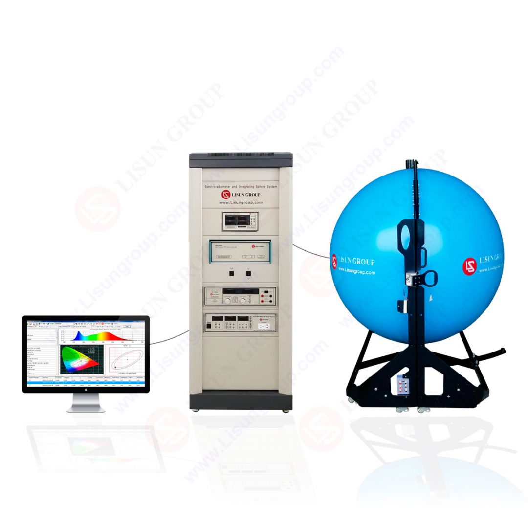 LPCE 2(LMS 9000) Spectrophotometer & Integrating Sphere Test System
Lisun Instruments Limited was found by LISUN GROUP in 2003. LISUN quality system has been strictly certified by ISO9001:2015. As a CIE Membership, LISUN products are designed based on CIE, IEC and other international or national standards. All products passed CE certificate and authenticated by the third party lab.
Our main products are Goniophotometer, Spectroradiometer, Integrating Sphere, LED Test Instruments, CFL Test Instruments, Photometer and Colorimeter, EMC & EMI Testing, Surge Generator, Electrical Safety Testing, Environmental Test Chamber, Waterproof Test , Dustproof Test Chamber, High and Low temperature Humidity Chamber, Plug and Switch Testing, AC and DC Power Supply.
Please feel free to contact us if you need any support.
Tech Dep: Service@Lisungroup.com, Cell/WhatsApp:+8615317907381
Sales Dep: Sales@Lisungroup.com, Cell/WhatsApp:+8618917996096
How to measure the characters of the fluorescent lamp in high frequency condition? How to verify the match relationship of the tube and ballast? These problems always trouble the fluorescent tubes manufacture enterprise and the third lab service company. Lisun Group supplies the following two solutions: IEC Standard Test Method and High Frequency Constant Current Equivalent Test Method.
1. IEC Standard Test Method:
Double end fluorescent lamp adopts the IEC 60081 (GB/T10682) and the single-ended fluorescent lamp adopts the IEC 60901 (GB/T17262), where in the standard of electricity parameters as in Fig 1. As we know the testing correctness of the photo & color parameters are based on the fact that the reference ballast, power and instrument in the detection circuit all comply with standards. If the reference ballast, power and instrument can’t meet the standard that means it can not supply the tube with standard working conditions. Then, not only the tested electricity parameter but also the photo & color parameters will deviate from the actual value obviously.
Fig 1 Preheating Method of Cathode High Frequency Fluorescent Lamp
Fig 1 does the high frequency tube test based on IEC Standard which required the High Frequency Power Source, Adjustable Reference Ballast and Lamp Preheat Assistant Source.
●High Frequency Power Supply (HFP-800): output power is 20~26kHz, the frequency should be kept in the range of ±2% at working. Output power is 0~580V.
●Adjustable Resistance Ballast (RB-3): impedance values of high frequency reference ballast which used by any high frequency lamp with regard to GB/T10682 (IEC 60081) and GB/T17262 (IEC60901), RB-3 conforms to the requirement of IEC60929.
●Lamp Preheat Assistant Source | Auxiliary Power Supply (LPS-3): Preheating method of cathode during the high frequency fluorescent lamp starting.
The above IEC Standard Test System is the necessary instrument not only to measure the photo & electricity parameters according to the standard of IEC 60081 and IEC 60901, but also to test the lumen and color parameters according to the standard of IEC 60929 (GB/T15144). Any national lighting electrical test centers must adopt the above test system if they need to do High frequency lamp such as T5 tube.
2. High Frequency Constant Current Equivalent Test Method:
Even though, the above Standard Test System can totally conform to the requirement of measuring the high frequency fluorescent lamp by IEC standard, due to the high price of this system, the small third lab service company and the most of manufactory company can’t cover the high cost, Lisun Group developed HCS-109A Adjustable High Frequency Reference Ballast which is an equivalent test method in comparison with IEC method. The typical schematic is shown as Fig 2, high frequency constant current source provides a continuously adjustable output current of 100mA ~ 500mA.
Fig 2 High Frequency Constant Current Equivalent Test Method
When connecting the circuit to turn on the lights, high frequency constant current source will deliver high-voltage pulse to start the lamp, the output frequency of high frequency constant current source is in 20~26kHz. The obvious shortage of equivalent method is due to the high constant current source output internal impedance. The large internal impedance of high frequency constant current source will cover the departure of tested lamp with respect to standard electrical parameters. It will take about 5%~ 30% tolerances when using LPCE-1 Fig 3 to test the photo, color and electricity parameters.
The above HCS-105A equipped with LPCE-2 High Precision Spectroradiometer Integrating Sphere System can test CCT, CRI, Spectrum, Lumen and electricity parameters for high frequency fluorescent lamp T5.
LPCE 2(LMS 9000) Spectrophotometer & Integrating Sphere Test SystemLisun Instruments Limited was found by LISUN GROUP in 2003. LISUN quality system has been strictly certified by ISO9001:2015. As a CIE Membership, LISUN products are designed based on CIE, IEC and other international or national standards. All products passed CE certificate and authenticated by the third party lab.
Our main products are Goniophotometer, Spectroradiometer, Integrating Sphere, LED Test Instruments, CFL Test Instruments, Photometer and Colorimeter, EMC & EMI Testing, Surge Generator, Electrical Safety Testing, Environmental Test Chamber, Waterproof Test , Dustproof Test Chamber, High and Low temperature Humidity Chamber, Plug and Switch Testing, AC and DC Power Supply.
Please feel free to contact us if you need any support.
Tech Dep: Service@Lisungroup.com, Cell/WhatsApp:+8615317907381
Sales Dep: Sales@Lisungroup.com, Cell/WhatsApp:+8618917996096
Sunday, February 16, 2020
How to measuring LED lamp start, run up time and flicker effectively?
Due to the LED solid-state lighting products have good luminous efficiency, long life and high reliability unique characteristics, so it’s became more popular by markets and customers. But at the same time, the LED solid lighting have fast response characteristics, it haven’t thermal inertia and afterglow effects, like traditional lamps, so it have big influence by current fluctuations, the current fluctuations affect the luminous flux output directly, the lighting flashing is the external expression of luminous flux change, that caused more and more people focus on lighting flashing issue. Dated 14th December, 2012, the EU officially released the (EU) NO 1194/2012 rules <Implementing rules of the European Parliament and the EU Council Directive 2009/125/EC on the eco-design requirements of directional lights, LED lights and related equipment requirements>.Compared with <European Parliament and Council Directive 2005/32/EC implementing rules for non-directional household lamps eco-design requirements> which posted by the European Commission Regulation (EC) NO 244/2009 Regulations dated 18th March, 2009, the new rules have complete mandatory and eco-design requirements. Start and Run-up time as the two indicators functional requirements in the industry has been more emphasis by manufacturers.
We just talked about the LED solid lighting product’s flicker effect, many people have no idea about this. The light source flashing is directly expression of luminous flux fluctuation, the light source is driving by AC current and pulsed DC current, luminous flux, illuminance or brightness change accordingly with the current amplitude of cyclical change. Normally, according to human eyes feeling, the flicker divided into Visiable Flicker and Invisible Flicker. When the frequency more than 100Hz, the human eyes can’t feeling the flicker, but it will cause eyestrain, headache etc, this is the flash effect, generally agreed that the flicker effect exists within 500Hz. For this issue, America Energy Star(ENERGY STAR lamps V1.0 draft 4 In the dimming performance requirements specified in the blink Conditions to be fulfilled, use all tools). As below figure:
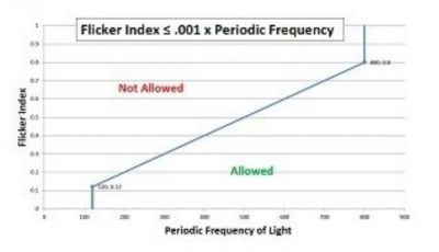
Light source flashing allowed range:
1、Frequency less than 100Hz;
2、Within 120Hz-800Hz frequency range, the F1<0.001 X frequency;
3、Frequency more than 800Hz, F1 have no requirements;
4、Frequency is uncertain, PF<30%;
Besides, the CFL lamp output frequency range should at 20-30KHz, or more than 40KHz.
The nature of light source flicker is luminous flux output fluctuations. When measuring light fluctuates with time change, not only the brightness curve can be tested, but also can test luminous flux curve or illumination curve which are under the same conditions. ENERGY STAR(V1.0)make the rules to measuring flicker’s requirements:
1、Power and instrumentation are need meet the requirements of LM-79-08;
2、Multi-channel oscilloscope with memory function, necessary need to add attenuation probe. The sampling rate is more than 2kHz, the sampling time is more than 100ms;
3、Photo detector V(入) Correction, and need meet the requirements of the corresponding time;
4、For the absolute value of the metering(absolute photometry): Need use integrating sphere when measuring of the absolute value; For relative value metering(relative photometry): To ensure that the detector is capable of measuring the relative light output, and only receives light from the light source to be measured;
Before measuring, the CFL lamps need light on 100 hours at least and it’s need preheat before testing. LED lamp needn’t lighting on, the environmental temperature range should at 25+/-5 degrees.
To meet EU ErP rules and Energy Star requirements, Lisun developed LSRF-2 Lamp Start, Run-up time and Flicker Test System. The hardware of this system included PH3000 Transient Photometer, LSP-500VAC Programmable AC Power Source Meter, IS-MA series Integrating Sphere, DC3005 DC Power Source and SLS series Standard Lamp; the software of this system included LST-3000 Lamp Start and Run-up Time Test and FLK-3000 Lamp Flick Test. PH3000 Transient Photometer is developed base on rapid sampling techniques, it’s fully meet EU and Energy Star relevant requirements. Combined with computer, it can measuring and record the fast change luminous flux waveform and others parameters. PH3000 applied with 12 Bytes, the maximum sampling rate of 10M Hz high-speed A / D. The PH3000 also can used as common illuminometer which can be widely used in light flux, brightness, illumination, etc. photometric detection and measurement. LSP-500VAC Programmable AC Sine Wave Power Source is a high-power, low pure sine wave distortion, high stability, integrated power supply source table, it’s especially suitable for as test power supply of electronic ballasts, energy saving lamps and other small power household appliances. And this system also included IS-1.5MA Integrating Sphere, DC3005 DC Power Source and SLS-50W Standard Light Source.
Lisun Instruments Limited was found by LISUN GROUP in 2003. LISUN quality system has been strictly certified by ISO9001:2015. As a CIE Membership, LISUN products are designed based on CIE, IEC and other international or national standards. All products passed CE certificate and authenticated by the third party lab.
Our main products are Goniophotometer, Spectroradiometer, Integrating Sphere, LED Test Instruments, CFL Test Instruments, Photometer and Colorimeter, EMC & EMI Testing, Surge Generator, Electrical Safety Testing, Environmental Test Chamber, Waterproof Test , Dustproof Test Chamber, High and Low temperature Humidity Chamber, Plug and Switch Testing, AC and DC Power Supply.
Please feel free to contact us if you need any support.
Tech Dep: Service@Lisungroup.com, Cell/WhatsApp:+8615317907381
Sales Dep: Sales@Lisungroup.com, Cell/WhatsApp:+8618917996096
We just talked about the LED solid lighting product’s flicker effect, many people have no idea about this. The light source flashing is directly expression of luminous flux fluctuation, the light source is driving by AC current and pulsed DC current, luminous flux, illuminance or brightness change accordingly with the current amplitude of cyclical change. Normally, according to human eyes feeling, the flicker divided into Visiable Flicker and Invisible Flicker. When the frequency more than 100Hz, the human eyes can’t feeling the flicker, but it will cause eyestrain, headache etc, this is the flash effect, generally agreed that the flicker effect exists within 500Hz. For this issue, America Energy Star(ENERGY STAR lamps V1.0 draft 4 In the dimming performance requirements specified in the blink Conditions to be fulfilled, use all tools). As below figure:
Light source flashing allowed range:
1、Frequency less than 100Hz;
2、Within 120Hz-800Hz frequency range, the F1<0.001 X frequency;
3、Frequency more than 800Hz, F1 have no requirements;
4、Frequency is uncertain, PF<30%;
Besides, the CFL lamp output frequency range should at 20-30KHz, or more than 40KHz.
The nature of light source flicker is luminous flux output fluctuations. When measuring light fluctuates with time change, not only the brightness curve can be tested, but also can test luminous flux curve or illumination curve which are under the same conditions. ENERGY STAR(V1.0)make the rules to measuring flicker’s requirements:
1、Power and instrumentation are need meet the requirements of LM-79-08;
2、Multi-channel oscilloscope with memory function, necessary need to add attenuation probe. The sampling rate is more than 2kHz, the sampling time is more than 100ms;
3、Photo detector V(入) Correction, and need meet the requirements of the corresponding time;
4、For the absolute value of the metering(absolute photometry): Need use integrating sphere when measuring of the absolute value; For relative value metering(relative photometry): To ensure that the detector is capable of measuring the relative light output, and only receives light from the light source to be measured;
Before measuring, the CFL lamps need light on 100 hours at least and it’s need preheat before testing. LED lamp needn’t lighting on, the environmental temperature range should at 25+/-5 degrees.
To meet EU ErP rules and Energy Star requirements, Lisun developed LSRF-2 Lamp Start, Run-up time and Flicker Test System. The hardware of this system included PH3000 Transient Photometer, LSP-500VAC Programmable AC Power Source Meter, IS-MA series Integrating Sphere, DC3005 DC Power Source and SLS series Standard Lamp; the software of this system included LST-3000 Lamp Start and Run-up Time Test and FLK-3000 Lamp Flick Test. PH3000 Transient Photometer is developed base on rapid sampling techniques, it’s fully meet EU and Energy Star relevant requirements. Combined with computer, it can measuring and record the fast change luminous flux waveform and others parameters. PH3000 applied with 12 Bytes, the maximum sampling rate of 10M Hz high-speed A / D. The PH3000 also can used as common illuminometer which can be widely used in light flux, brightness, illumination, etc. photometric detection and measurement. LSP-500VAC Programmable AC Sine Wave Power Source is a high-power, low pure sine wave distortion, high stability, integrated power supply source table, it’s especially suitable for as test power supply of electronic ballasts, energy saving lamps and other small power household appliances. And this system also included IS-1.5MA Integrating Sphere, DC3005 DC Power Source and SLS-50W Standard Light Source.
Lisun Instruments Limited was found by LISUN GROUP in 2003. LISUN quality system has been strictly certified by ISO9001:2015. As a CIE Membership, LISUN products are designed based on CIE, IEC and other international or national standards. All products passed CE certificate and authenticated by the third party lab.
Our main products are Goniophotometer, Spectroradiometer, Integrating Sphere, LED Test Instruments, CFL Test Instruments, Photometer and Colorimeter, EMC & EMI Testing, Surge Generator, Electrical Safety Testing, Environmental Test Chamber, Waterproof Test , Dustproof Test Chamber, High and Low temperature Humidity Chamber, Plug and Switch Testing, AC and DC Power Supply.
Please feel free to contact us if you need any support.
Tech Dep: Service@Lisungroup.com, Cell/WhatsApp:+8615317907381
Sales Dep: Sales@Lisungroup.com, Cell/WhatsApp:+8618917996096
Subscribe to:
Comments (Atom)